18 Jan 2023

Coordinated Holiday Lights - box 4

The forth box features the BeagleBone Black (bbb), the IoT Relay (I might as well use them since I already have them), and also has hard-wired ethernet. The bbb features TI's AM335x Sitara SoC which is based on a single-core, 32-bit, ARM, Cortex-A8. This device will control the lights on the eastern driveway gate.

Parts:

Unlike the RPi (or other RPi-like boards), the bbb is quite clear in its documentation that it can not be powered via its expansion pins. Therefore this build uses the 5V transformer that came with the board and plugs into the bbb's mini-B USB connector.

The bbb has both a soldered-on eMMC flash, and takes an SDcard. By default, if the firmware detects a valid image on the eMMC, its preference is to boot from that device over the SDcard. I want to always have my system boot from SDcard. Therefore on first boot I hold down the BOOT button in order to get it to boot from the SDcard and not the eMMC. Once running I then erased the eMMC flash. Without a valid image in eMMC the bbb's firmware will elect instead to boot from the SDcard.

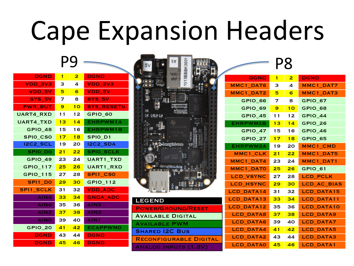
On the one hand it's nice that so many SBCs have standardized around a common header. On the other hand it would have been nicer if the industry had standardized around a header that provided access to more of the buses and pins that projects could use. Of course in my case I only need access to 1 GPIO pin, therefore the standard "RPi 40-pin header" is more than adequate. However some projects can find the 40 pins of the RPi header limiting. If you find yourself in that sort of situation, you'll appreciate the bbb's staggering 92 pins:


Similar to the RPi, the bbb's kernel is well-loved, therefore the kernel knows a lot about its GPIOs:

  1
  2
  3
  4
  5
  6
  7
  8
  9
 10
 11
 12
 13
 14
 15
 16
 17
 18
 19
 20
 21
 22
 23
 24
 25
 26
 27
 28
 29
 30
 31
 32
 33
 34
 35
 36
 37
 38
 39
 40
 41
 42
 43
 44
 45
 46
 47
 48
 49
 50
 51
 52
 53
 54
 55
 56
 57
 58
 59
 60
 61
 62
 63
 64
 65
 66
 67
 68
 69
 70
 71
 72
 73
 74
 75
 76
 77
 78
 79
 80
 81
 82
 83
 84
 85
 86
 87
 88
 89
 90
 91
 92
 93
 94
 95
 96
 97
 98
 99
100
101
102
103
104
105
106
107
108
109
110
111
112
113
114
115
116
117
118
119
120
121
122
123
124
125
126
127
128
129
130
131
132
133
root@beaglebone:~# gpioinfo 
gpiochip0 - 32 lines:
        line   0: "[ethernet]"       unused   input  active-high 
        line   1: "[ethernet]"       unused   input  active-high 
        line   2: "P9_22 [spi0_sclk]" unused input active-high 
        line   3: "P9_21 [spi0_d0]" unused input active-high 
        line   4: "P9_18 [spi0_d1]" unused input active-high 
        line   5: "P9_17 [spi0_cs0]" unused input active-high 
        line   6:  "[sd card]"         "cd"   input   active-low [used]
        line   7: "P9_42A [ecappwm0]" unused input active-high 
        line   8: "P8_35 [hdmi]" unused input active-high 
        line   9: "P8_33 [hdmi]" unused input active-high 
        line  10: "P8_31 [hdmi]" unused input active-high 
        line  11: "P8_32 [hdmi]" unused input active-high 
        line  12: "P9_20 [i2c2_sda]" unused input active-high 
        line  13: "P9_19 [i2c2_scl]" unused input active-high 
        line  14: "P9_26 [uart1_rxd]" unused input active-high 
        line  15: "P9_24 [uart1_txd]" unused input active-high 
        line  16: "[ethernet]"       unused   input  active-high 
        line  17: "[ethernet]"       unused   input  active-high 
        line  18:      "[usb]"       unused   input  active-high 
        line  19:     "[hdmi]"       unused   input  active-high 
        line  20:     "P9_41B"       unused   input  active-high 
        line  21: "[ethernet]"       unused   input  active-high 
        line  22: "P8_19 [ehrpwm2a]" unused input active-high 
        line  23: "P8_13 [ehrpwm2b]" unused input active-high 
        line  24:       "[NC]"       unused   input  active-high 
        line  25:       "[NC]"       unused   input  active-high 
        line  26:      "P8_14"       unused   input  active-high 
        line  27:      "P8_17"       unused   input  active-high 
        line  28: "[ethernet]"       unused   input  active-high 
        line  29: "[ethernet]"       unused   input  active-high 
        line  30: "P9_11 [uart4_rxd]" unused input active-high 
        line  31: "P9_13 [uart4_txd]" unused input active-high
gpiochip1 - 32 lines:
        line   0: "P8_25 [emmc]" unused input active-high 
        line   1:     "[emmc]"       unused   input  active-high 
        line   2: "P8_5 [emmc]" unused input active-high 
        line   3: "P8_6 [emmc]" unused input active-high 
        line   4: "P8_23 [emmc]" unused input active-high 
        line   5: "P8_22 [emmc]" unused input active-high 
        line   6: "P8_3 [emmc]" unused input active-high 
        line   7: "P8_4 [emmc]" unused input active-high 
        line   8:       "[NC]"       unused   input  active-high 
        line   9:       "[NC]"       unused   input  active-high 
        line  10:       "[NC]"       unused   input  active-high 
        line  11:       "[NC]"       unused   input  active-high 
        line  12:      "P8_12"       unused   input  active-high 
        line  13:      "P8_11"       unused   input  active-high 
        line  14:      "P8_16"       unused   input  active-high 
        line  15:      "P8_15"       unused   input  active-high 
        line  16:     "P9_15A"       unused   input  active-high 
        line  17:      "P9_23"       unused   input  active-high 
        line  18: "P9_14 [ehrpwm1a]" unused input active-high 
        line  19: "P9_16 [ehrpwm1b]" unused input active-high 
        line  20:     "[emmc]"       unused   input  active-high 
        line  21: "[usr0 led]" "beaglebone:green:heartbeat" output active-high [used]
        line  22: "[usr1 led]" "beaglebone:green:mmc0" output active-high [used]
        line  23: "[usr2 led]" "beaglebone:green:usr2" output active-high [used]
        line  24: "[usr3 led]" "beaglebone:green:usr3" output active-high [used]
        line  25:     "[hdmi]"  "interrupt"   input  active-high [used]
        line  26:      "[usb]"       unused   input  active-high 
        line  27: "[hdmi audio]" "enable" output active-high [used]
        line  28:      "P9_12"       unused   input  active-high 
        line  29:      "P8_26"       unused   input  active-high 
        line  30: "P8_21 [emmc]" unused input active-high 
        line  31: "P8_20 [emmc]" unused input active-high 
gpiochip2 - 32 lines:
        line   0:     "P9_15B"       unused   input  active-high 
        line   1:      "P8_18"       unused   input  active-high 
        line   2:       "P8_7"       unused   input  active-high 
        line   3:       "P8_8"       unused   input  active-high 
        line   4:      "P8_10"       unused   input  active-high 
        line   5:       "P8_9"       unused   input  active-high 
        line   6: "P8_45 [hdmi]" unused input active-high 
        line   7: "P8_46 [hdmi]" unused input active-high 
        line   8: "P8_43 [hdmi]" unused input active-high 
        line   9: "P8_44 [hdmi]" unused input active-high 
        line  10: "P8_41 [hdmi]" unused input active-high 
        line  11: "P8_42 [hdmi]" unused input active-high 
        line  12: "P8_39 [hdmi]" unused input active-high 
        line  13: "P8_40 [hdmi]" unused input active-high 
        line  14: "P8_37 [hdmi]" unused input active-high 
        line  15: "P8_38 [hdmi]" unused input active-high 
        line  16: "P8_36 [hdmi]" unused input active-high 
        line  17: "P8_34 [hdmi]" unused input active-high 
        line  18: "[ethernet]"       unused   input  active-high 
        line  19: "[ethernet]"       unused   input  active-high 
        line  20: "[ethernet]"       unused   input  active-high 
        line  21: "[ethernet]"       unused   input  active-high 
        line  22: "P8_27 [hdmi]" unused input active-high 
        line  23: "P8_29 [hdmi]" unused input active-high 
        line  24: "P8_28 [hdmi]" unused input active-high 
        line  25: "P8_30 [hdmi]" unused input active-high 
        line  26:     "[emmc]"       unused   input  active-high 
        line  27:     "[emmc]"       unused   input  active-high 
        line  28:     "[emmc]"       unused   input  active-high 
        line  29:     "[emmc]"       unused   input  active-high 
        line  30:     "[emmc]"       unused   input  active-high 
        line  31:     "[emmc]"       unused   input  active-high
gpiochip3 - 32 lines:
        line   0: "[ethernet]"       unused   input  active-high 
        line   1: "[ethernet]"       unused   input  active-high 
        line   2: "[ethernet]"       unused   input  active-high 
        line   3: "[ethernet]"       unused   input  active-high 
        line   4: "[ethernet]"       unused   input  active-high 
        line   5:     "[i2c0]"       unused   input  active-high 
        line   6:     "[i2c0]"       unused   input  active-high 
        line   7:      "[emu]"       unused   input  active-high 
        line   8:      "[emu]"       unused   input  active-high 
        line   9: "[ethernet]"       unused   input  active-high 
        line  10: "[ethernet]"       unused   input  active-high 
        line  11:       "[NC]"       unused   input  active-high 
        line  12:       "[NC]"       unused   input  active-high 
        line  13:      "[usb]"       unused   input  active-high 
        line  14: "P9_31 [spi1_sclk]" unused input active-high 
        line  15: "P9_29 [spi1_d0]" unused input active-high 
        line  16: "P9_30 [spi1_d1]" unused input active-high 
        line  17: "P9_28 [spi1_cs0]" unused input active-high 
        line  18: "P9_42B [ecappwm0]" unused input active-high 
        line  19:      "P9_27"       unused   input  active-high 
        line  20:     "P9_41A"       unused   input  active-high 
        line  21:      "P9_25"       unused   input  active-high 
        line  22:       "[NC]"       unused   input  active-high 
        line  23:       "[NC]"       unused   input  active-high 
        line  24:       "[NC]"       unused   input  active-high 
        line  25:       "[NC]"       unused   input  active-high 
        line  26:       "[NC]"       unused   input  active-high 
        line  27:       "[NC]"       unused   input  active-high 
        line  28:       "[NC]"       unused   input  active-high 
        line  29:       "[NC]"       unused   input  active-high 
        line  30:       "[NC]"       unused   input  active-high 
        line  31:       "[NC]"       unused   input  active-high

Arbitrarily, I've decided that I'm going to use GPIO_45. GPIO_45 is located on connector P8, pin 11. Looking through the information provided above we see that P8_11 is found at gpiochip1, line 13. No datasheets, schematics, or reference manuals required! Wiring up a prototype, we can perform the following quick test:

1
root@raspberrypi3-64:~# gpioset gpiochip1 13=1

Wait a minute! The load didn't turn on, why aren't the lights on after running the above command?

At first I assumed I had done something wrong: bad wiring or maybe bad GPIO? I checked all the wiring; looks okay. Then I tried a different GPIO; same result. Maybe try a GPIO on the P9 connnector; still doesn't work. One of the times I ran the gpioset program I did hear the relay click, although the lights didn't turn on, which led me to believe I had found the correct GPIO/pin association. After a bit of searching around I came across the --mode=wait option of gpioset.

As long as the gpioset program is running, it will control the GPIO line, but when it terminates, it releases the line. Coincidentally, on all the other SBCs I've used so far, after gpioset terminates, the line stays where it had been set. As a result the lights are turned on and stay on. On the bbb, however, after the gpioset program terminates the GPIO line doesn't continue on in the state in which it was set, rather it returns to its previous "OFF" state. Since code is fast and relays are slow, most times the relay doesn't even click over (never mind the lights coming on) before the relay is de-activated. Therefore when testing gpio lines with gpioset, it would be best to test with the following and then terminate the program with Ctrl-C:

1
root@raspberrypi3-64:~# gpioset --mode=wait gpiochip1 13=1


fritzing:


finished box:


before install:


after install:


16 Jan 2023

Coordinated Holiday Lights - box 3

The third box that I put together has the rock-pi-e SBC, uses the IoT Relay from Digital Loggers, and has ethernet wired to its location. The rock-pi-e features the Rockchip rk3328  which is a quad-core, 64-bit, ARM Cortex-A53 SoC. I intend to use this device to power the lights on the western driveway gate.

Parts:

Having wired ethernet to this (or any) location is a huge improvement over WiFi or ethernet-over-power (i.e. powerline) schemes. Running ethernet isn't cheap, but I believe it's worth it. That being the case, this box doesn't need a powerline adapter, but it does need a weatherproof gland for ethernet. As is the issue with plugs and outlets, trying to find a gland that can open large enough to accomodate the RJ-45 ethernet jack to pass through, but that also close down enough to seal the cable are hard to find. The ideal solution is the cut the ethernet cable, pass it through a gland, then clamp the connector on afterwards. Maybe someday I'll be forced to create my own ethernet cables (and at that point I'll wonder why I ever did it any other way!) but for today Adafruit comes to the rescue with these intelligent and easy to use ethernet glands. The cable on the outside plugs into the gland on one side, and on the inside of the box is another connector for a short cable to run from the gland to the SBC.


The rest of the box construction is pretty straight-forward. Comments that I have regarding the IoT Relay, the power supply, and the Wago connectors are covered in other posts in this series. As with the Raspberry Pi 3, this device can also be powered through its GPIO pins. Similar to the imx233-olinuxino-maxi, the rock-pi-e also does not have factory-provided MAC addresses, but this is easily remedied.

This SoC seems to have the same fate as the older i.MX233 device despite being much more modern. It doesn't look like anyone has gotten around to associating this board's GPIO pins with their names:

  1
  2
  3
  4
  5
  6
  7
  8
  9
 10
 11
 12
 13
 14
 15
 16
 17
 18
 19
 20
 21
 22
 23
 24
 25
 26
 27
 28
 29
 30
 31
 32
 33
 34
 35
 36
 37
 38
 39
 40
 41
 42
 43
 44
 45
 46
 47
 48
 49
 50
 51
 52
 53
 54
 55
 56
 57
 58
 59
 60
 61
 62
 63
 64
 65
 66
 67
 68
 69
 70
 71
 72
 73
 74
 75
 76
 77
 78
 79
 80
 81
 82
 83
 84
 85
 86
 87
 88
 89
 90
 91
 92
 93
 94
 95
 96
 97
 98
 99
100
101
102
103
104
105
106
107
108
109
110
111
112
113
114
115
116
117
118
119
120
121
122
123
124
125
126
127
128
129
130
131
132
133
root@rock-pi-e:~# gpioinfo
gpiochip0 - 32 lines:
        line   0:      unnamed "vcc-wifi-regulator" output active-low [used]
        line   1:      unnamed       unused   input  active-high 
        line   2:      unnamed       unused   input  active-high 
        line   3:      unnamed       unused   input  active-high 
        line   4:      unnamed       unused   input  active-high 
        line   5:      unnamed       unused   input  active-high 
        line   6:      unnamed       unused   input  active-high 
        line   7:      unnamed       unused   input  active-high 
        line   8:      unnamed       unused   input  active-high 
        line   9:      unnamed       unused   input  active-high 
        line  10:      unnamed       unused   input  active-high 
        line  11:      unnamed       unused   input  active-high 
        line  12:      unnamed       unused   input  active-high 
        line  13:      unnamed       unused   input  active-high 
        line  14:      unnamed       unused   input  active-high 
        line  15:      unnamed       unused   input  active-high 
        line  16:      unnamed       unused   input  active-high 
        line  17:      unnamed       unused   input  active-high 
        line  18:      unnamed       unused   input  active-high 
        line  19:      unnamed       unused   input  active-high 
        line  20:      unnamed       unused   input  active-high 
        line  21:      unnamed       unused   input  active-high 
        line  22:      unnamed       unused   input  active-high 
        line  23:      unnamed       unused   input  active-high 
        line  24:      unnamed       unused   input  active-high 
        line  25:      unnamed       unused   input  active-high 
        line  26:      unnamed       unused   input  active-high 
        line  27:      unnamed       unused   input  active-high 
        line  28:      unnamed       unused   input  active-high 
        line  29:      unnamed       unused   input  active-high 
        line  30:      unnamed "sdmmc-regulator" output active-low [used]
        line  31:      unnamed       unused   input  active-high
gpiochip1 - 32 lines:
        line   0:      unnamed       unused   input  active-high 
        line   1:      unnamed       unused   input  active-high 
        line   2:      unnamed       unused   input  active-high 
        line   3:      unnamed       unused   input  active-high 
        line   4:      unnamed       unused   input  active-high 
        line   5:      unnamed       unused   input  active-high 
        line   6:      unnamed       unused   input  active-high 
        line   7:      unnamed       unused   input  active-high 
        line   8:      unnamed       unused   input  active-high 
        line   9:      unnamed       unused   input  active-high 
        line  10:      unnamed       unused   input  active-high 
        line  11:      unnamed       unused   input  active-high 
        line  12:      unnamed       unused   input  active-high 
        line  13:      unnamed       unused   input  active-high 
        line  14:      unnamed       unused   input  active-high 
        line  15:      unnamed       unused   input  active-high 
        line  16:      unnamed       unused   input  active-high 
        line  17:      unnamed       unused   input  active-high 
        line  18:      unnamed       unused   input  active-high 
        line  19:      unnamed       unused   input  active-high 
        line  20:      unnamed       unused   input  active-high 
        line  21:      unnamed       unused   input  active-high 
        line  22:      unnamed       unused   input  active-high 
        line  23:      unnamed       unused   input  active-high 
        line  24:      unnamed       unused   input  active-high 
        line  25:      unnamed       unused   input  active-high 
        line  26:      unnamed       unused   input  active-high 
        line  27:      unnamed       unused   input  active-high 
        line  28:      unnamed       unused   input  active-high 
        line  29:      unnamed       unused   input  active-high 
        line  30:      unnamed       unused   input  active-high 
        line  31:      unnamed       unused   input  active-high 
gpiochip2 - 32 lines:
        line   0:      unnamed       unused   input  active-high 
        line   1:      unnamed       unused   input  active-high 
        line   2:      unnamed       unused   input  active-high 
        line   3:      unnamed       unused  output  active-high 
        line   4:      unnamed       unused   input  active-high 
        line   5:      unnamed       unused   input  active-high 
        line   6:      unnamed  "interrupt"   input  active-high [used]
        line   7:      unnamed       unused   input  active-high 
        line   8:      unnamed       unused   input  active-high 
        line   9:      unnamed       unused   input  active-high 
        line  10:      unnamed       unused   input  active-high 
        line  11:      unnamed       unused   input  active-high 
        line  12:      unnamed       unused   input  active-high 
        line  13:      unnamed       unused   input  active-high 
        line  14:      unnamed       unused   input  active-high 
        line  15:      unnamed       unused   input  active-high 
        line  16:      unnamed       unused   input  active-high 
        line  17:      unnamed       unused   input  active-high 
        line  18:      unnamed       unused   input  active-high 
        line  19:      unnamed       unused   input  active-high 
        line  20:      unnamed       unused   input  active-high 
        line  21:      unnamed       unused   input  active-high 
        line  22:      unnamed       unused   input  active-high 
        line  23:      unnamed       unused   input  active-high
        line  24:      unnamed       unused   input  active-high 
        line  25:      unnamed       unused   input  active-high 
        line  26:      unnamed       unused   input  active-high 
        line  27:      unnamed       unused   input  active-high 
        line  28:      unnamed       unused   input  active-high 
        line  29:      unnamed       unused   input  active-high 
        line  30:      unnamed       unused   input  active-high 
        line  31:      unnamed       unused   input  active-high
gpiochip3 - 32 lines:
        line   0:      unnamed       unused   input  active-high 
        line   1:      unnamed       unused   input  active-high 
        line   2:      unnamed       unused   input  active-high 
        line   3:      unnamed       unused   input  active-high 
        line   4:      unnamed       unused   input  active-high 
        line   5:      unnamed      "blue:"  output   active-low [used]
        line   6:      unnamed       unused   input  active-high 
        line   7:      unnamed "vcc-host-5v-regulator" output active-high [used]
        line   8:      unnamed       unused   input  active-high 
        line   9:      unnamed       unused   input  active-high 
        line  10:      unnamed       unused   input  active-high 
        line  11:      unnamed       unused   input  active-high 
        line  12:      unnamed       unused   input  active-high 
        line  13:      unnamed       unused   input  active-high 
        line  14:      unnamed       unused   input  active-high 
        line  15:      unnamed       unused   input  active-high 
        line  16:      unnamed       unused   input  active-high 
        line  17:      unnamed       unused   input  active-high 
        line  18:      unnamed       unused   input  active-high 
        line  19:      unnamed       unused   input  active-high 
        line  20:      unnamed       unused   input  active-high 
        line  21:      unnamed       unused   input  active-high 
        line  22:      unnamed       unused   input  active-high 
        line  23:      unnamed       unused   input  active-high 
        line  24:      unnamed       unused   input  active-high 
        line  25:      unnamed       unused   input  active-high 
        line  26:      unnamed       unused   input  active-high 
        line  27:      unnamed       unused   input  active-high 
        line  28:      unnamed       unused   input  active-high 
        line  29:      unnamed       unused   input  active-high 
        line  30:      unnamed       unused   input  active-high 
        line  31:      unnamed       unused   input  active-high

Thankfully the Radxa Wiki page on this SoC's GPIOs provides all the information we need without having to dive into schematics and reference manuals. Simply locate the pin you want to use, then run the various values through the equation they provide and you're done. As with the Raspberry Pi 3, I've decided to use pin 40 for the relay signal. Since I'm using a V1.2 rock-pi-e board I consult the drawing for V1.2:


Pin 40 is known as GPIO2_C7. The format of the naming is as follows:

Therefore GPIO2_C7 tells us that the pin is on gpiochip2, pin 8*2 + 7 = 23.

Fritzing:


Here's how the finished box looks:


Before installation:


After installation:


Coordinated Holiday Lights - box 2

The second box that I put together features an Olimex iMX233-OlinuXino-MAXI for the SBC, connects to the network via an ethernet-over-power device, and uses a Digital Loggers "IoT Relay" device. The MAXI features the i.MX233 SoC which has a 32-bit, ARM9 arm926ej-s at its core. My intention is to use this device to run the lights on the bush in front of the house.

Parts:

When I was first thinking of this project (a couple years ago), I thought the "IoT Relay" from Digital Loggers would be a good device around-which to create my design. I was hoping it would keep me from having to do a lot of cutting and splicing of mains power cables. However, in order to get cables into and out of the box, cutting and splicing is unavoidable. So while these are neat devices, and I did end up using a couple of them (I had already bought them for this project), they're a little over-kill. Simple relays (as in box 1) would be more than adequate, and would save a bunch of space. Nevertheless, the IoT Relay has 4 NEMA 5-15P outlets: 3 of which are controlled by the control signal, 1 of which is "always on" (provided the device itself has power and is switched on). 2 of the 3 controlled outlets are "normally OFF" and the 3rd outlet is "normally ON". A removable screw terminal provides the signal by which to control the relay.

To supply power for the MAXI, I simply plugged the 12V 1A wall wart that came with the board into the IoT Relay's "Always ON" outlet.

The piggy-back NEMA 5-15P to C13 do-hicky was quite a lucky find! The IoT Relay has a C14 connector, and I needed a second 5-15P for the powerline adapter, so this device was able to solve both problems.

One small thing that tripped me up momentarily when working with the MAXI is that it doesn't have a manufacturer-assigned, static MAC address. I noticed this while setting up and testing my DHCP configuration, this board kept being assigned an IP address from the DHCP pool instead of the static IP I wanted it to have. Fortunately setting up a static, user-defined, locally-administered, unicast, MAC address isn't too difficult if it only needs to be set when Linux runs (if you need your bootloader to know/setup the MAC address, then other arrangements need to be made).

The iMX233-OlinuXino-MAXI is designed around the Freescale (now NXP) i.MX233 SoC. This SoC has an arm926ej-s at its core. The arm926ej-s was introduced in 2001; the i.MX233 SoC was brought to market in 2009. Despite its age, this SoC is still being produced, and Olimex is still building and selling boards around this device. Unfortunately, being an older device, its Linux kernel support isn't up to par. One of the issues is due to the fact it is so old, meaning it receives less active development. When it was introduced and support was added for it in the Linux kernel, the kernel had a completely different GPIO subsystem. In the intervening years that subsystem has been entirely re-written. All the newer, more popular, regularly-used SoCs all had their GPIO subsystems well integrated with the new subsystem. Older SoCs compile, but that's about it. As a result the kernel's GPIO information is rather lacking:

  1
  2
  3
  4
  5
  6
  7
  8
  9
 10
 11
 12
 13
 14
 15
 16
 17
 18
 19
 20
 21
 22
 23
 24
 25
 26
 27
 28
 29
 30
 31
 32
 33
 34
 35
 36
 37
 38
 39
 40
 41
 42
 43
 44
 45
 46
 47
 48
 49
 50
 51
 52
 53
 54
 55
 56
 57
 58
 59
 60
 61
 62
 63
 64
 65
 66
 67
 68
 69
 70
 71
 72
 73
 74
 75
 76
 77
 78
 79
 80
 81
 82
 83
 84
 85
 86
 87
 88
 89
 90
 91
 92
 93
 94
 95
 96
 97
 98
 99
100
root@imx233-olinuxino-maxi:~# gpioinfo 
gpiochip0 - 32 lines:
        line   0:      unnamed       unused   input  active-high 
        line   1:      unnamed       unused   input  active-high 
        line   2:      unnamed       unused   input  active-high 
        line   3:      unnamed       unused   input  active-high 
        line   4:      unnamed       unused   input  active-high 
        line   5:      unnamed       unused   input  active-high 
        line   6:      unnamed       unused   input  active-high 
        line   7:      unnamed       unused   input  active-high 
        line   8:      unnamed       unused   input  active-high 
        line   9:      unnamed       unused   input  active-high 
        line  10:      unnamed       unused   input  active-high 
        line  11:      unnamed       unused   input  active-high 
        line  12:      unnamed       unused   input  active-high 
        line  13:      unnamed       unused   input  active-high 
        line  14:      unnamed       unused   input  active-high 
        line  15:      unnamed       unused   input  active-high 
        line  16:      unnamed       unused   input  active-high 
        line  17:      unnamed "regulators:regulator@0" output active-high [used]
        line  18:      unnamed       unused   input  active-high 
        line  19:      unnamed       unused   input  active-high 
        line  20:      unnamed       unused   input  active-high 
        line  21:      unnamed       unused   input  active-high 
        line  22:      unnamed       unused   input  active-high 
        line  23:      unnamed       unused   input  active-high 
        line  24:      unnamed       unused   input  active-high 
        line  25:      unnamed       unused   input  active-high 
        line  26:      unnamed       unused   input  active-high 
        line  27:      unnamed       unused   input  active-high 
        line  28:      unnamed       unused   input  active-high 
        line  29:      unnamed       unused   input  active-high 
        line  30:      unnamed       unused   input  active-high 
        line  31:      unnamed       unused   input  active-high
gpiochip1 - 32 lines:
        line   0:      unnamed       unused   input  active-high 
        line   1:      unnamed       unused   input  active-high 
        line   2:      unnamed       unused   input  active-high 
        line   3:      unnamed       unused   input  active-high 
        line   4:      unnamed       unused   input  active-high 
        line   5:      unnamed       unused   input  active-high 
        line   6:      unnamed       unused   input  active-high 
        line   7:      unnamed       unused   input  active-high 
        line   8:      unnamed       unused   input  active-high 
        line   9:      unnamed       unused   input  active-high 
        line  10:      unnamed       unused   input  active-high 
        line  11:      unnamed       unused   input  active-high 
        line  12:      unnamed       unused   input  active-high 
        line  13:      unnamed       unused   input  active-high 
        line  14:      unnamed       unused   input  active-high 
        line  15:      unnamed       unused   input  active-high 
        line  16:      unnamed       unused   input  active-high 
        line  17:      unnamed       unused   input  active-high 
        line  18:      unnamed       unused   input  active-high 
        line  19:      unnamed       unused   input  active-high 
        line  20:      unnamed       unused   input  active-high 
        line  21:      unnamed       unused   input  active-high 
        line  22:      unnamed       unused   input  active-high 
        line  23:      unnamed       unused   input  active-high 
        line  24:      unnamed       unused   input  active-high 
        line  25:      unnamed       unused   input  active-high 
        line  26:      unnamed       unused  output  active-high 
        line  27:      unnamed       unused   input  active-high 
        line  28:      unnamed       unused   input  active-high 
        line  29:      unnamed       unused   input  active-high 
        line  30:      unnamed       unused   input  active-high 
        line  31:      unnamed       unused   input  active-high 
gpiochip2 - 32 lines:
        line   0:      unnamed       unused   input  active-high 
        line   1:      unnamed      "green"  output  active-high [used]
        line   2:      unnamed       unused   input  active-high 
        line   3:      unnamed       unused   input  active-high 
        line   4:      unnamed       unused   input  active-high 
        line   5:      unnamed       unused   input  active-high 
        line   6:      unnamed       unused   input  active-high 
        line   7:      unnamed       unused   input  active-high 
        line   8:      unnamed       unused   input  active-high 
        line   9:      unnamed       unused   input  active-high 
        line  10:      unnamed       unused   input  active-high 
        line  11:      unnamed       unused   input  active-high 
        line  12:      unnamed       unused   input  active-high 
        line  13:      unnamed       unused   input  active-high 
        line  14:      unnamed       unused   input  active-high 
        line  15:      unnamed       unused   input  active-high 
        line  16:      unnamed       unused   input  active-high 
        line  17:      unnamed       unused   input  active-high 
        line  18:      unnamed       unused   input  active-high 
        line  19:      unnamed       unused   input  active-high 
        line  20:      unnamed       unused   input  active-high 
        line  21:      unnamed       unused   input  active-high 
        line  22:      unnamed       unused   input  active-high 
        line  23:      unnamed       unused   input  active-high 
        line  24:      unnamed       unused   input  active-high 
        line  25:      unnamed       unused   input  active-high 
        line  26:      unnamed       unused   input  active-high 
        line  27:      unnamed       unused   input  active-high 
        line  28:      unnamed       unused   input  active-high 
        line  29:      unnamed       unused   input  active-high 
        line  30:      unnamed       unused   input  active-high 
        line  31:      unnamed       unused   input  active-high

Therefore, in order to figure out how its GPIOs connect to the SoC, we're going to have to do some digging into the board's schematics, then into the SoC's Reference Manual.

Thankfully, being open hardware, the schematics are publicly available (thank you Olimex!). The MAXI has a large, 40-pin, male connector on its side which is described in the schematic. Pretty much any GPIO line could be used, I decided to use the one labeled "PIN30".

Looking at the schematic:


We can see that PIN30 is connected to pin #28 of the board connector. We can also see that PIN30 connects to the SoC's pin 81, and the the SoC knows this pin as GPMI_CE1N.

[NOTE: There seems to be a little mistake in this schematic since it shows the SoC's pin 81 not connected to anything. Thankfully that's not the case, and we can associate the SoC pin with the connector pin by the common wire name: PIN30]

Now if we look at the SoC's Reference Manual and search for GPMI_CE1N we find (on page 37-28):


and we also find (on page 37-7):


Both of these confirm that the SoC pin known as GPMI_CE1N is found in GPIO bank 2, pin 27.

[NOTE: This SoC comes in 2 form factors: 128-pin QFP and 169-pin BGA. The schematics from Olimex show that they're using the MCIMX233CAG4C specifically. Page 41-1 of the Reference Manual shows that the CAG4C is the 128-pin LQFP (actually it shows that the CAG4B is the 128-pin LQFP, but searching on the Internet shows that the CAG4C is simply a later revision of the same device). When you're looking at the pin descriptions in the Reference Manual, make sure you're looking at the tables for the QFP specifically and not the BGA, otherwise you'll get the wrong GPIO bank/pin]


Performing the following simple test on the target board with everything wired up correctly proves we've found the right place:

1
root@imx233-olinuxino-maxi:~# gpioset gpiochip2 27=1

One thing that I did notice about this device compared to the other SBCs that I used for these boxes is that this SoC does run noticeably slower than the others. If I used systemd for the init system the device would run just fine for a while, but then become completely unresponsive for quite a while (perhaps 30 seconds?). Then it would run perfectly fine for many minutes, but then be unresponsive. When it was possible to type in commands again, running cat /proc/loadavg would show a lot of recent activity. Switching to sysvinit gives a system that doesn't have unresponsive gaps.

I had decided that I was going to install an ssh server on all these devices so I could interact with them "in the field" should I so desire. As part of any device's first boot with an ssh server installed, a bunch of security keys need to be generated. Without exaggeration, installing an ssh server on this device causes the first boot to take well over 5 minutes before a command line is reached as the device generates/calculates its ssh keys. Maybe using dropbear would be better? I didn't check. My guess is that dropbear would need to generate its own initial keys as well, so it would probably run just as poorly on first boot?

I suspect the real source of the problem is the the random number generator code in the kernel. Random numbers produce the best security keys, but generating randomness from deterministic devices is difficult. Over the years the Linux kernel has had several iterations of the random-generating subsystem as people find issues. Most modern SoCs now come with circuitry specifically designed to generate randomness in order to feed the pool of entropy that is used to generate secure keys (for example). This new code assumes such units exist, but in older hardware they either don't exist, or the kernel's drivers haven't been updated to support the new functionality. In any case, generating the randomness required to create cryptographically secure keys (by some definition of "secure") takes a long time.

Conceptually box2 could be described by the following Fritzing diagram:


Here's how the box looked partway through the build (I don't seem to have a pic of it when it was done):


Before installation:


After installation:


14 Jan 2023

Coordinated Holiday Lights - box 1

The first box that I put together features a RaspberryPi 3 and accesses the network via ethernet-over-power (i.e. powerline ethernet). The RaspberryPi 3 runs on the Broadcom BCM2837; a 64-bit, quad-core, ARM Cortex-A53 SoC. My intention is to use this device to run the lights on the house and deck.

Parts:

One of the nice things about the RasberryPi is that, like so many such similar boards, it can be powered via its header pins. Therefore a nice, compact switching power supply to convert between mains voltage and the 5V3A can be plugged directly into either of the 5V pins of the RPi's 40-pin header. I chose the Mean Well RS-15-5 switching power supply. Simply connect the 3 mains wires on one side, and take 5V and ground off from the remaining pins; plug these 2 into the RPi's header and you've got power. One significant little detail that I did stumble over with these power supplies is the "adjustment" screw. When I first plugged the power supply and the RPi together, the RPi couldn't boot. Hooking up a console cable I could see some of the messages coming through okay at the start, but then there would be a whole bunch of garbled characters on the console. Garbled and legible text would come and go as the device booted. It was quite odd. It was as if the baud rate was fluctuating as the board ran. The leds on the board would come on, blink a little bit, then obviously start over again. It was clear the board was in a reboot cycle. I was about to try a different device (fortunately I had bought a couple) when I noticed the "adjustment" screw. I never did end up measuring anything, but I noticed the screw was turned all the way to the left (counter-clockwise). On a hunch I turned the screw all the way to the right (clockwise) then suddenly everything worked just perfectly.

The standard RPi header has quite a few GPIOs, and any one of which could be used for controlling the relay. I chose (completely arbitrarily) to use GPIO21, pin 40. As part of prototyping, you can test out controlling pin 40 with the gpioset program which is part of the libgpiod-tools Yocto package. The gpioinfo program can be used to dump out the Linux kernel's understanding of which GPIOs go where. I'm running this command on a Linux kernel 5.15.56:

 1
 2
 3
 4
 5
 6
 7
 8
 9
10
11
12
13
14
15
16
17
18
19
20
21
22
23
24
25
26
27
28
29
30
31
32
33
34
35
36
37
38
39
40
41
42
43
44
45
46
47
48
49
50
51
52
53
54
55
56
57
58
59
60
61
62
63
64
65
root@raspberrypi3-64:~# gpioinfo 
gpiochip0 - 54 lines:
        line   0:     "ID_SDA"       unused   input  active-high 
        line   1:     "ID_SCL"       unused   input  active-high 
        line   2:       "SDA1"       unused   input  active-high 
        line   3:       "SCL1"       unused   input  active-high 
        line   4:  "GPIO_GCLK"       unused   input  active-high 
        line   5:      "GPIO5"       unused   input  active-high 
        line   6:      "GPIO6"       unused   input  active-high 
        line   7:  "SPI_CE1_N"       unused   input  active-high 
        line   8:  "SPI_CE0_N"       unused   input  active-high 
        line   9:   "SPI_MISO"       unused   input  active-high 
        line  10:   "SPI_MOSI"       unused   input  active-high 
        line  11:   "SPI_SCLK"       unused   input  active-high 
        line  12:     "GPIO12"       unused   input  active-high 
        line  13:     "GPIO13"       unused   input  active-high 
        line  14:       "TXD1"       unused   input  active-high 
        line  15:       "RXD1"       unused   input  active-high 
        line  16:     "GPIO16"       unused   input  active-high 
        line  17:     "GPIO17"       unused   input  active-high 
        line  18:     "GPIO18"       unused   input  active-high 
        line  19:     "GPIO19"       unused   input  active-high 
        line  20:     "GPIO20"       unused   input  active-high 
        line  21:     "GPIO21"       unused   input  active-high
        line  22:     "GPIO22"       unused   input  active-high 
        line  23:     "GPIO23"       unused   input  active-high 
        line  24:     "GPIO24"       unused   input  active-high 
        line  25:     "GPIO25"       unused   input  active-high 
        line  26:     "GPIO26"       unused   input  active-high 
        line  27:     "GPIO27"       unused   input  active-high 
        line  28: "HDMI_HPD_N"       unused   input  active-high 
        line  29: "STATUS_LED_G" "led0" output active-high [used]
        line  30:       "CTS0"       unused   input  active-high 
        line  31:       "RTS0"       unused   input  active-high 
        line  32:       "TXD0"       unused   input  active-high 
        line  33:       "RXD0"       unused   input  active-high 
        line  34:    "SD1_CLK"       unused   input  active-high 
        line  35:    "SD1_CMD"       unused   input  active-high 
        line  36:  "SD1_DATA0"       unused   input  active-high 
        line  37:  "SD1_DATA1"       unused   input  active-high 
        line  38:  "SD1_DATA2"       unused   input  active-high 
        line  39:  "SD1_DATA3"       unused   input  active-high 
        line  40:   "PWM0_OUT"       unused   input  active-high 
        line  41:   "PWM1_OUT"       unused   input  active-high 
        line  42:    "ETH_CLK"       unused   input  active-high 
        line  43:   "WIFI_CLK"       unused   input  active-high 
        line  44:       "SDA0"       unused   input  active-high 
        line  45:       "SCL0"       unused   input  active-high 
        line  46:   "SMPS_SCL"       unused   input  active-high 
        line  47:   "SMPS_SDA"       unused  output  active-high 
        line  48:   "SD_CLK_R"       unused   input  active-high 
        line  49:   "SD_CMD_R"       unused   input  active-high 
        line  50: "SD_DATA0_R"       unused   input  active-high 
        line  51: "SD_DATA1_R"       unused   input  active-high 
        line  52: "SD_DATA2_R"       unused   input  active-high 
        line  53: "SD_DATA3_R"       unused   input  active-high 
gpiochip1 - 8 lines:
        line   0:      "BT_ON"       unused  output  active-high 
        line   1:      "WL_ON"       unused  output  active-high 
        line   2:  "PWR_LED_R"       "led1"  output   active-low [used]
        line   3:    "LAN_RUN"       unused  output  active-high 
        line   4:         "NC"       unused   input  active-high 
        line   5:  "CAM_GPIO0" "cam1_regulator" output active-high [used]
        line   6:  "CAM_GPIO1"       unused  output  active-high 
        line   7:         "NC"       unused   input  active-high

As you can see, some wonderful kernel developer has done a great job associating the various pins with their common names. One doesn't have to consult any datasheets or schematics to see that if I want to control GPIO21, all that is required is to fiddle with pin 21 of gpiochip0:

1
root@raspberrypi3-64:~# gpioset 0 21=1

If everything is wired up correctly, then your relay should now be active. The gpioset utility also understands chip names as well, so instead of saying "gpioset 0 21=1" you could also write "gpioset gpiochip0 21=1". To turn off the relay, run the same command setting "21=0".

When working with relays, make sure to keep the mains and the electronics sides of the board separate. On the electronics side hook up the other 5V pin from the RPi header (i.e. the 5V pin not being used to supply power to the RPi from the switching power supply) to the relay's "Vin" pin, ground from the RPi to the relay's "GND" pin, and hook up the RPi's GPIO 21 (pin 40) to the relay's "Sig" pin. On the mains side make sure you come directly from mains power into the relay's "Common" connector. Relays have 2 modes: if you want your microcontroller to turn something on when it activates the relay, then connect the load to the "NO" (normally open) side. If you want your load to turn off when the microcontroller activates the relay, then connect your load to the "NC" (normally closed) side. In my case I want the lights to come on when the microcontroller activates the relay, therefore I connect my load to the NO side.


HUGE NOTE: By convention: in the world of home electrical wiring in North America the black wire is the hot wire, the white is neutral, and the green is ground. However in the world of electronics the black wire is ground and the red wire is VIN (12V, 5V, 3V3, 1V8 etc). When looking at the following diagrams and pictures do not confuse the black, hot, home-wiring, AC wires with the black, ground, electronics, DC ground wires -- they are separate!


The conceptual drawing of the complete box in Fritzing looks as follows:


The completed box looks like (oops! looks like I forgot to remove the serial console cable before taking this pic!):


Before installation:

After installation:


12 Jan 2023

Coordinated Holiday Lights - intro

I like putting lights up around the property for the holidays, and have run power to various locations over the years in support of this endeavour. I now have lights on the house (which includes the deck), on a bush in front of the house, on the gates (where the driveway meets the road), and on some fencing leading to the barn. In time I would like to put up even more lights in more locations. Currently each set of lights plugs into power individually, and (since I don't want these lights to be on all the time) each set of lights has its own way of turning off during the day and turning on at night. For variety, some locations use off-the-shelf light-sensor plugs, and other locations use off-the-shelf timer plugs.


Now it's time to get fancy.

During the day all these lights are off; at night they're all on. But in between being all off or all on, each set of lights in each of these locations changes state at random times. In fact sometimes a set of lights controlled by a light-sensor changes state a couple times before settling down to one state or another. Wouldn't it be nice if they all turned on and off at the same time?

One way to solve this problem would be to run extension cords to and from all these lights and then plug them all in at only one location. This would work on smaller properties, but unfortunately the distances between all the lights on my property doesn't make this practical for me. Another option would be to buy "smart" sockets... but where's the fun in that?

The light-sensor plugs have a couple drawbacks:

  • if the light sensor and the lights it controls are in too close of proximity to each other, then they end up in a perpetual cycle, at night, of turning on then off then on then off...
  • if the light sensor is close to a driveway or road, then headlights from vehicles going past at night will trip the sensor and turn off the lights for a minute or two
  • the specific light-sensor plugs that I'm using have multiple settings that are selected by pushing a button on the device; the initial, power-on setting is to stay off; I like the "dawn to dusk" setting; unfortunately the device doesn't save your preference across power-cycles, therefore every time there is a power blip I need to go around to each device and set it back to "dawn to dusk" mode

  The timer plugs also have a couple drawbacks:

  • the amount of daylight changes every day, so each timer would need to be manually modified every couple weeks otherwise the lights they control will either be on for a portion of the day (when they should be off), and/or will be off for some part of the night (when they should be on)
  • in my experience, many of these timers keep time very poorly; as a result, a timer that is set to turn on or off every day at a specific time ends up drifting away from that time very noticeably and very quickly
  • any power outage will end up adjusting the "current time" of the device by the length of the power outage, resulting in more trips around the property to adjust the timers

It's interesting that the winter solstice occurs in the middle of "holiday lights" season. So if you are using timers then you will want to be increasing the amount of "on"-time as you approach the solstice, then contract it as you leave the solstice behind.

Both of these solutions (light sensors and timers) have drawbacks. But even if one of them was a clear winner, lights in different locations would still turn on and off at different times; all the lights wouldn't be coordinated. The amount of light falling on different parts of the property varies quite a bit; so if I used light-sensor plugs everywhere, different areas would still turn on and off at different times. On the other hand, if I used timers everywhere it would be hard to precisely synchronize multiple timers. Even if they did start out perfectly synchronized, over time they would drift, and would need to be adjusted regularly for nothing else than to adjust to the amount of daylight. In other words, using timers everywhere would also not result in all the lights turning on and off simultaneously.

As a result I've decided to make something myself. I want to create a device that can be used outdoors, and provides an outlet whose on/off state is remotely controllable. This way I can send one command from a central controller and have all the lights turn on or off (as appropriate) simultaneously. Additionally, if I wanted to control specific outlets individually I would like to be able to do that as well.

Currently I will need 6 such devices (house + deck, bush, east gate, west gate, east fence, and west fence). As an added twist, I've decided to use a different single board computer (SBC) for each unit I put together. There are literally hundreds of Linux-capable SBCs from which to choose, so why not give a bunch of them a try?

23 Feb 2021

GDB+OpenOCD an ADI Target with The Yocto Project/Openembedded

UPDATE: unfortunately the "fix" I suggest below doesn't work :-( It seemed to work yesterday because the half-dozen times or so that I used it, the connection, coincidentally, was robust. But running it many many dozens of times today, I do see it failing. As does the cross-gdb binary supplied by ADI. So there's something wrong with the connection between openocd and gdb. Sometimes they connect just fine, other times something goes wrong. Probably an issue with the closed-source openocd binary, or an issue with the openocd configuration files for the JTAG or the target.


I'm working with a board from Analog Devices. Unfortunately it's not possible to use upstream openocd. You have to use the openocd binary that comes with their Developer's Kit.

Although I'm forced to use their openocd binary, I wanted to be able to use my own cross-gdb; one that I could build as part of my Yocto/OE-generated SDK. But whenever I tried connecting my cross-gdb (arm-oe-linux-gnueabi-gdb) to their openocd I would get errors, and further debugging wasn't possible.

I start their openocd and get the regular openocd information:

# bin/openocd --search share/openocd/scripts/ -f interface/ice1000.cfg -f target/adspsc58x.cfg
Open On-Chip Debugger (Analog Devices CCES 2.8.0 OpenOCD 0.9.0-g5030ad7) 0.9.0
Licensed under GNU GPL v2
Report bugs to <processor.tools.support@analog.com>
adapter speed: 1000 kHz
Info : transports supported by the debug adapter: "jtag", "swd"
Info : auto-select transport "jtag"
halt and restart using CTI
trst_only separate trst_push_pull
Info : ICE-1000 firmware version is 1.0.2
Info : clock speed 1000 kHz
Info : JTAG tap: adspsc58x.adjc tap/device found: 0x128080cb (mfg: 0x065, part: 0x2808, ver: 0x1)
Info : JTAG tap: adspsc58x.dap enabled
Info : adspsc58x.dap: hardware has 3 breakpoints, 2 watchpoints
Info : adspsc58x.dap: but you can only set 1 watchpoint

I then startup the arm-oe-linux-gnueabi-gdb that was built as part of the Yocto/OE SDK that I generated:

$ arm-oe-linux-gnueabi-gdb u-boot-sc589-ezkit
GNU gdb (GDB) 8.2
Copyright (C) 2018 Free Software Foundation, Inc.
License GPLv3+: GNU GPL version 3 or later <http://gnu.org/licenses/gpl.html>
This is free software: you are free to change and redistribute it.
There is NO WARRANTY, to the extent permitted by law.
Type "show copying" and "show warranty" for details.
This GDB was configured as "--host=x86_64-oesdk-linux --target=arm-oe-linux-gnueabi".
Type "show configuration" for configuration details.
For bug reporting instructions, please see:
<http://www.gnu.org/software/gdb/bugs/>.
Find the GDB manual and other documentation resources online at:
    <http://www.gnu.org/software/gdb/documentation/>.

For help, type "help".
Type "apropos word" to search for commands related to "word"...
Reading symbols from u-boot-sc589-ezkit...done.
(gdb) 

So far, so good. However, the moment I connect the two… In gdb I get:

(gdb) target remote :3333
Remote debugging using :3333
warning: remote target does not support file transfer, attempting to access files from local filesystem.
warning: Unable to find dynamic linker breakpoint function.
GDB will be unable to debug shared library initializers
and track explicitly loaded dynamic code.

and in openocd I get:

Info : accepting 'gdb' connection on tcp/3333
Warn : system reset not supported for ADSP-SC58x silicon revision 0.0 and 0.1
Info : ttbcr 0ttbr0 0ttbr1 0
Info : adspsc58x.dap rev 1, partnum c05, arch f, variant 0, implementor 41
Info : number of cache level 1
Info : adspsc58x.dap cluster 0 core 0 mono core
target state: halted
target halted in Thumb state due to debug-request, current mode: Supervisor
cpsr: 0x800001f3 pc: 0x00004810
MMU: disabled, D-Cache: disabled, I-Cache: disabled
semihosting is enabled
Error: Timeout waiting for cortex_a_exec_opcode
Error: Timeout waiting for InstrCompl=1
Warn : negative acknowledgment, but no packet pending
Error: Timeout waiting for InstrCompl=1
Warn : negative acknowledgment, but no packet pending
Error: Timeout waiting for InstrCompl=1
Warn : negative acknowledgment, but no packet pending
Error: Timeout waiting for InstrCompl=1
Warn : negative acknowledgment, but no packet pending
Error: Timeout waiting for InstrCompl=1

Searching the Internet for solutions I was excited to find that the gdb "set sysroot <path>" was supposed to solve my problems, but it didn't. However the "set solib-absolute-prefix <path>" did! Simply set this option to the absolute path of the Yocto/OE-generated rootfs and everything works again.

$ arm-oe-linux-gnueabi-gdb u-boot-sc589-ezkit
GNU gdb (GDB) 8.2
Copyright (C) 2018 Free Software Foundation, Inc.
License GPLv3+: GNU GPL version 3 or later <http://gnu.org/licenses/gpl.html>
This is free software: you are free to change and redistribute it.
There is NO WARRANTY, to the extent permitted by law.
Type "show copying" and "show warranty" for details.
This GDB was configured as "--host=x86_64-oesdk-linux --target=arm-oe-linux-gnueabi".
Type "show configuration" for configuration details.
For bug reporting instructions, please see:
<http://www.gnu.org/software/gdb/bugs/>.
Find the GDB manual and other documentation resources online at:
    <http://www.gnu.org/software/gdb/documentation/>.

For help, type "help".
Type "apropos word" to search for commands related to "word"...
Reading symbols from u-boot-sc589-ezkit...done.
(gdb) set solib-absolute-prefix /z/2.6-build-thud/sc589-ezkit/build/tmp-glibc/work/adsp_sc589_ezkit-oe-linux-gnueabi/core-image-minimal/1.0-r0/rootfs/
(gdb) target remote :3333
Remote debugging using :3333
warning: Unable to find dynamic linker breakpoint function.
GDB will be unable to debug shared library initializers
and track explicitly loaded dynamic code.
0x00005392 in ?? ()
(gdb) load init-sc589-ezkit.elf 
Loading section .text, size 0x510 lma 0x20080000
Start address 0x20080024, load size 1296
Transfer rate: 24 KB/sec, 1296 bytes/write.
(gdb) c
Continuing.
^C
Program received signal SIGINT, Interrupt.
0x00005394 in ?? ()
(gdb) load u-boot-sc589-ezkit
Loading section .text, size 0x2d59c lma 0xc2200000
Loading section .rodata, size 0xb3a7 lma 0xc222d59c
Loading section .hash, size 0x18 lma 0xc2238944
Loading section .data, size 0x2458 lma 0xc223895c
Loading section .got.plt, size 0xc lma 0xc223adb4
Loading section .u_boot_list, size 0x894 lma 0xc223adc0
Loading section .rel.dyn, size 0x7308 lma 0xc223b654
Loading section .dynsym, size 0x30 lma 0xc224295c
Loading section .dynstr, size 0x1 lma 0xc224298c
Loading section .dynamic, size 0x90 lma 0xc2242990
Loading section .interp, size 0x14 lma 0xc2242a20
Loading section .gnu.hash, size 0x18 lma 0xc2242a34
Start address 0xc2200000, load size 272968
Transfer rate: 32 KB/sec, 10498 bytes/write.
(gdb) c
Continuing.

NOTE: both the init-sc589-ezkit.elf and the u-boot-sc589-ezkit binaries are the ones I have built via Yocto/OE. So it's possible to build and use your own cross-gdb, initializer (init-sc589-ezkit-elf), and u-boot that are built with Yocto/OE.

Notice, as well, that I still get those warnings about not being able to find dynamic linker breakpoints, but at least I'm able to proceed.