27 Jan 2023

Coordinated Holiday Lights - base software

My goal is to put together a set of devices that will allow me to coordinate the turning on and turning off of various holiday lights around a large property. These devices are plugged into mains power and provide an outlet (to which the load is connected) whose state is controlled by the electronics inside the box. By this time I've built four such boxes and it is time to start thinking about software. I'm using Linux-capable single board computers (SBCs) in each box. As an added twist I've decided to use a different SBC in each box. So far I've used:

  • raspberry pi 3
  • olimex imx233-olinuxino-maxi
  • rock pi e
  • beagleboard black

When a manufacturer puts out an SBC, they always provide some sort of software to show off the device. If they're going to claim their new SBC has certain capabilities, then they need to provide some software in order to benchmark their claims. This software is more often than not provided as a monolithic binary image: "download this file, flash it to an SDcard, insert the SDcard into the SBC, and apply power".

Since there is no single, universally accepted, correct, Linux image/system to use, vendors are free to put together their images however they wish (or however then can). Some are deb-based, others use rpm; some don't even have a package manager. Some use sysvinit, others systemd. Some use X, others will use Wayland. Some will use busybox components, others will use the full utilities (coreutils). Some are based on recent versions of software, others are based on software that is quite old the day the SBC is released. All of these choices affect the user experience. How do you start a daemon? How do you configure networking? How do you set the state of a GPIO pin? These procedures are all different depending on which choices were made earlier. For example: the seemingly simple task of setting a GPIO will be frustrating for the user if the SBC has an old kernel and the user's search finds them instructions for a recent kernel, or instructions that use a tool that isn't available in the manufacturer's image, or instructions that use an option for a tool that wasn't enabled in the tool that is in the manufacturer's image.

Putting together an image is not a trivial activity. Maintaining an image and keeping it up-to-date throughout the lifecycle of a product (which includes development!) is even more work. As it turns out, there are tools that can be used to create an image. Some image-creation tools can even help with the on-going maintenance of an image over its lifetime. But is the manufacturer aware of these tools when they put together their image? Did they use these tools, or slap something together in-house? Is the image they create using common idioms and conventions, or is it an anomaly with quirks unlike anything else you'll find anywhere else in the Linux world? There is a cost that goes along with learning how to use a tool (and learning how to use it well), slapping something together haphazardly often feels faster and easier (especially in the short term).

If a user buys an SBC because they want to use it for a specific project they have in mind, they usually don't want to spend any time putting together their own images; they want to get going on their project, and rarely is their project "to put together an image for this SBC". Therefore the easiest way to get started is to use the manufacturer-provided image. However, the software the manufacturer provides will only include whatever the manufacturer thought was important in order to quantify whatever it is they wish to benchmark. These manufacturer-provided images are "show-off" images, they're not "get your project done" images. Does your project require an mqtt client for example? That could be an issue, because the vendor wasn't benchmarking messaging performance, so the image doesn't include any mqtt client libraries.

"Here's the board, here's a link to download the image we've put together, and here's the press release highlighting our impressive achievements." One thing these press releases will never highlight is that their impressive performance numbers were not achieved using upstream software. The bootloader is most likely a fork, the kernel is almost certainly a fork, and any software they're benchmarking (and the system libraries upon which it depends) are often forks.

Does the manufacturer-provided image include all the libraries on top of which you need to build your software? Does it include all the services or daemons on which your software relies? Probably not, so now what do you do? How would you go about building additional software for your device the manufacturer doesn't include? Is there even an SDK? Even if one board does provide a library you need, would another board from a completely different manufacturer also provide that same library so you could run your project on both boards? And if both boards do provide that library, are they API-compatible, or do you need to write your software to support both an old and a new API of that library?

Increasingly in recent years, one popular way around the problem of how to develop additional software for different vendor-provided images that have different software stacks is to completely eschew compiled languages altogether! "Forget compilers, forget cross-development and all its challenges; that's way too difficult for you. We'll provide you with an interpreted language runtime, and you can script your way to project happiness. By the way, you're comfortable writing in Lua, right?". Another "solution" to this problem is to simply provide native compilers in the vendor-provided image so you can do your development work right on the target board itself. That's crazy! These solutions could work for very simple scenarios where the software only needs to do one simple task, but exciting projects need the ability to do real development.

These types of problems (and more!) are solved with The Yocto Project.

The Yocto Project (colloquially: "Yocto") is a suite of tools to create your own embedded Linux distributions. You choose each and every piece of software you want included on your device. You choose whether you want sysvinit or systemd, X or Wayland, and so on. Then you choose the board you wish to target, and it builds your distribution/image for that board as well as all required dependencies. Perform the same build but target a different board (often a one-line change in your build configuration), and now you have the exact same software (versions and all) running on a completely different device. If you need to develop software for your product, Yocto will generate board-specific, image-specific SDKs for you, or you could use devtool to build, upload, and generate test images as you write your code.

Of course there are some caveats. Not all combinations of all software work on every board. Sometimes a specific SoC does not have upstream support so you're forced to use vendor bootloaders and vendor kernels if you want anything to work. But the entire software stack above the kernel can be synchronized. This means that the list of packages installed into every board's image will not only be the same, but the versions will be the same as well. If your SoCs can run with the upstream kernel and bootloader, then the entire software stack can be synchronized amongst all your devices. The procedure to set the IP address on one board will work on all your boards. The tools and options you use to set a GPIO pin on one board will work on all your boards. Any software you write only needs to target one API, because all your boards are using those same libraries, and the same versions of all those libraries.

For my specific project I don't need any graphics and won't be using any display devices, so I start with a basic core-image-base. Over the years I've collected together a set of tools and utilities I like to have on my images, so I include those. In this specific case I like when all my devices have their clocks synchronized so I'm going to install chrony and configure all of them to point to my internal time server. I want them to know where they are, so I install a bunch of timezone packages (tzdata-core and tzdata-posix) and set the DEFAULT_TIMEZONE to the one in which I live. I want all my devices to have an ssh server so I add that to my distribution, and because I'll be working with GPIOs in this project I also add libgpiod-tools. Since power could be lost at any time and I want to minimize the possibility of corrupt root disks I also add read-only-rootfs to my distro's EXTRA_IMAGE_FEATURES. After that I start my builds for my various boards, test these base images, and they all work great. I'm ready to start writing the software that's going to give these boards the magic they need to make my project a reality!

For many embedded software teams, using a set of SBCs with no two of them the same in a project (or being is a situation where their chosen board goes EOL or becomes impossible to procure and a new board will need to be found) would be very challenging. Using a vendor-supplied image for anything other than the specific things the vendor wants to highlight is problematic. Also, each and every vendor-supplied image is different in significant ways from every other SBC's image. As a result hobbyists and professionals alike tend to use the same board/SoC everywhere for every project regardless of whether or not it's a good fit... and hope it will be available for a long time.

With Yocto, developing for several SBCs simultaneously is simple. Creating the same image for wildly different SoCs/boards and writing code for all of them simultaneously is how Yocto was designed to be used. Of course, if you want to use the same board everywhere, it also works great for that scenario as well. It brings conformity to your user experience regardless of underlying hardware. It provides you with the set of development tools you need to get your project done, and to maintain your project going forward.

18 Jan 2023

Coordinated Holiday Lights - box 4

The forth box features the BeagleBone Black (bbb), the IoT Relay (I might as well use them since I already have them), and also has hard-wired ethernet. The bbb features TI's AM335x Sitara SoC which is based on a single-core, 32-bit, ARM, Cortex-A8. This device will control the lights on the eastern driveway gate.

Parts:

Unlike the RPi (or other RPi-like boards), the bbb is quite clear in its documentation that it can not be powered via its expansion pins. Therefore this build uses the 5V transformer that came with the board and plugs into the bbb's mini-B USB connector.

The bbb has both a soldered-on eMMC flash, and takes an SDcard. By default, if the firmware detects a valid image on the eMMC, its preference is to boot from that device over the SDcard. I want to always have my system boot from SDcard. Therefore on first boot I hold down the BOOT button in order to get it to boot from the SDcard and not the eMMC. Once running I then erased the eMMC flash. Without a valid image in eMMC the bbb's firmware will elect instead to boot from the SDcard.

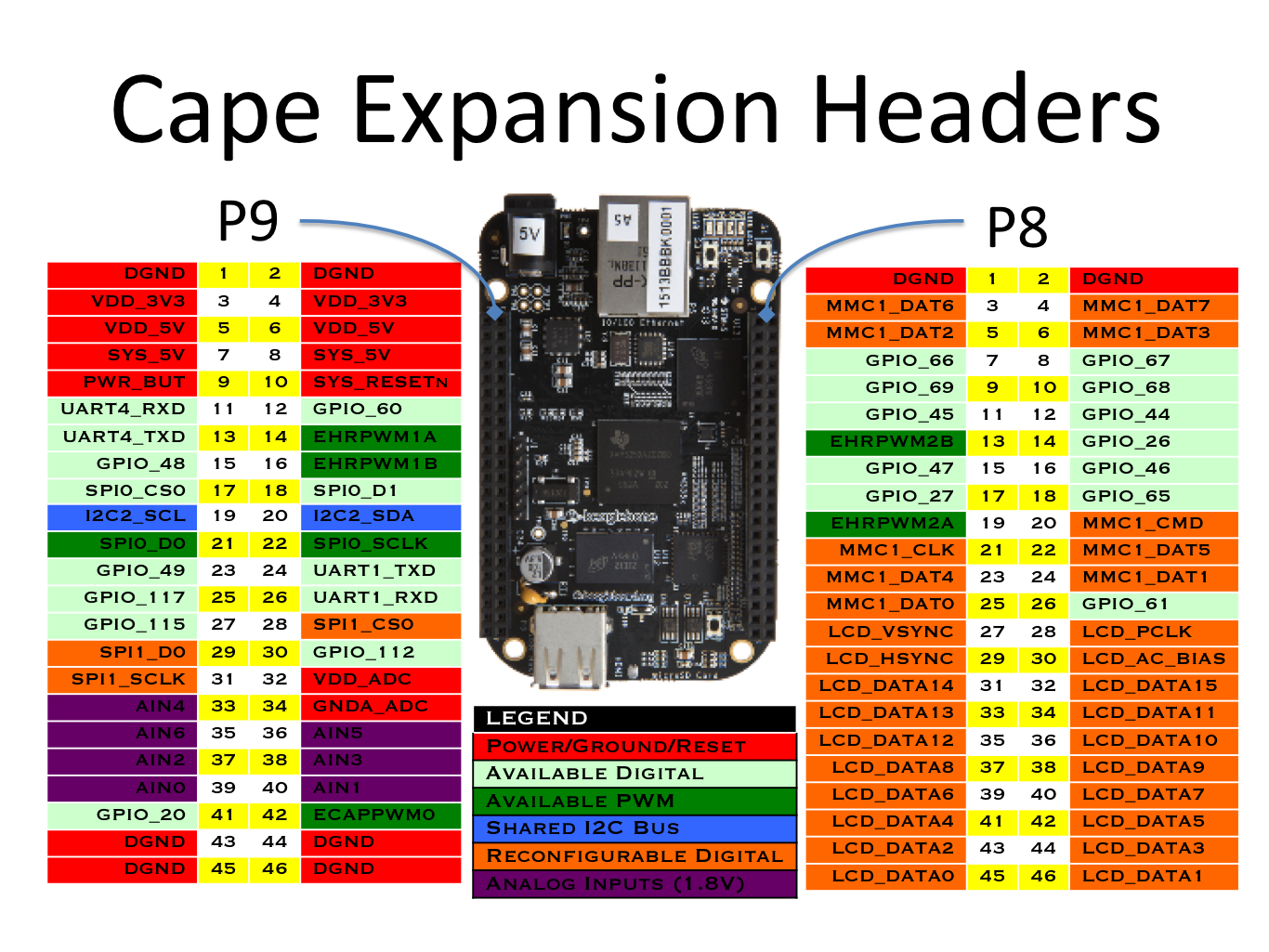
On the one hand it's nice that so many SBCs have standardized around a common header. On the other hand it would have been nicer if the industry had standardized around a header that provided access to more of the buses and pins that projects could use. Of course in my case I only need access to 1 GPIO pin, therefore the standard "RPi 40-pin header" is more than adequate. However some projects can find the 40 pins of the RPi header limiting. If you find yourself in that sort of situation, you'll appreciate the bbb's staggering 92 pins:


Similar to the RPi, the bbb's kernel is well-loved, therefore the kernel knows a lot about its GPIOs:

  1
  2
  3
  4
  5
  6
  7
  8
  9
 10
 11
 12
 13
 14
 15
 16
 17
 18
 19
 20
 21
 22
 23
 24
 25
 26
 27
 28
 29
 30
 31
 32
 33
 34
 35
 36
 37
 38
 39
 40
 41
 42
 43
 44
 45
 46
 47
 48
 49
 50
 51
 52
 53
 54
 55
 56
 57
 58
 59
 60
 61
 62
 63
 64
 65
 66
 67
 68
 69
 70
 71
 72
 73
 74
 75
 76
 77
 78
 79
 80
 81
 82
 83
 84
 85
 86
 87
 88
 89
 90
 91
 92
 93
 94
 95
 96
 97
 98
 99
100
101
102
103
104
105
106
107
108
109
110
111
112
113
114
115
116
117
118
119
120
121
122
123
124
125
126
127
128
129
130
131
132
133
root@beaglebone:~# gpioinfo 
gpiochip0 - 32 lines:
        line   0: "[ethernet]"       unused   input  active-high 
        line   1: "[ethernet]"       unused   input  active-high 
        line   2: "P9_22 [spi0_sclk]" unused input active-high 
        line   3: "P9_21 [spi0_d0]" unused input active-high 
        line   4: "P9_18 [spi0_d1]" unused input active-high 
        line   5: "P9_17 [spi0_cs0]" unused input active-high 
        line   6:  "[sd card]"         "cd"   input   active-low [used]
        line   7: "P9_42A [ecappwm0]" unused input active-high 
        line   8: "P8_35 [hdmi]" unused input active-high 
        line   9: "P8_33 [hdmi]" unused input active-high 
        line  10: "P8_31 [hdmi]" unused input active-high 
        line  11: "P8_32 [hdmi]" unused input active-high 
        line  12: "P9_20 [i2c2_sda]" unused input active-high 
        line  13: "P9_19 [i2c2_scl]" unused input active-high 
        line  14: "P9_26 [uart1_rxd]" unused input active-high 
        line  15: "P9_24 [uart1_txd]" unused input active-high 
        line  16: "[ethernet]"       unused   input  active-high 
        line  17: "[ethernet]"       unused   input  active-high 
        line  18:      "[usb]"       unused   input  active-high 
        line  19:     "[hdmi]"       unused   input  active-high 
        line  20:     "P9_41B"       unused   input  active-high 
        line  21: "[ethernet]"       unused   input  active-high 
        line  22: "P8_19 [ehrpwm2a]" unused input active-high 
        line  23: "P8_13 [ehrpwm2b]" unused input active-high 
        line  24:       "[NC]"       unused   input  active-high 
        line  25:       "[NC]"       unused   input  active-high 
        line  26:      "P8_14"       unused   input  active-high 
        line  27:      "P8_17"       unused   input  active-high 
        line  28: "[ethernet]"       unused   input  active-high 
        line  29: "[ethernet]"       unused   input  active-high 
        line  30: "P9_11 [uart4_rxd]" unused input active-high 
        line  31: "P9_13 [uart4_txd]" unused input active-high
gpiochip1 - 32 lines:
        line   0: "P8_25 [emmc]" unused input active-high 
        line   1:     "[emmc]"       unused   input  active-high 
        line   2: "P8_5 [emmc]" unused input active-high 
        line   3: "P8_6 [emmc]" unused input active-high 
        line   4: "P8_23 [emmc]" unused input active-high 
        line   5: "P8_22 [emmc]" unused input active-high 
        line   6: "P8_3 [emmc]" unused input active-high 
        line   7: "P8_4 [emmc]" unused input active-high 
        line   8:       "[NC]"       unused   input  active-high 
        line   9:       "[NC]"       unused   input  active-high 
        line  10:       "[NC]"       unused   input  active-high 
        line  11:       "[NC]"       unused   input  active-high 
        line  12:      "P8_12"       unused   input  active-high 
        line  13:      "P8_11"       unused   input  active-high 
        line  14:      "P8_16"       unused   input  active-high 
        line  15:      "P8_15"       unused   input  active-high 
        line  16:     "P9_15A"       unused   input  active-high 
        line  17:      "P9_23"       unused   input  active-high 
        line  18: "P9_14 [ehrpwm1a]" unused input active-high 
        line  19: "P9_16 [ehrpwm1b]" unused input active-high 
        line  20:     "[emmc]"       unused   input  active-high 
        line  21: "[usr0 led]" "beaglebone:green:heartbeat" output active-high [used]
        line  22: "[usr1 led]" "beaglebone:green:mmc0" output active-high [used]
        line  23: "[usr2 led]" "beaglebone:green:usr2" output active-high [used]
        line  24: "[usr3 led]" "beaglebone:green:usr3" output active-high [used]
        line  25:     "[hdmi]"  "interrupt"   input  active-high [used]
        line  26:      "[usb]"       unused   input  active-high 
        line  27: "[hdmi audio]" "enable" output active-high [used]
        line  28:      "P9_12"       unused   input  active-high 
        line  29:      "P8_26"       unused   input  active-high 
        line  30: "P8_21 [emmc]" unused input active-high 
        line  31: "P8_20 [emmc]" unused input active-high 
gpiochip2 - 32 lines:
        line   0:     "P9_15B"       unused   input  active-high 
        line   1:      "P8_18"       unused   input  active-high 
        line   2:       "P8_7"       unused   input  active-high 
        line   3:       "P8_8"       unused   input  active-high 
        line   4:      "P8_10"       unused   input  active-high 
        line   5:       "P8_9"       unused   input  active-high 
        line   6: "P8_45 [hdmi]" unused input active-high 
        line   7: "P8_46 [hdmi]" unused input active-high 
        line   8: "P8_43 [hdmi]" unused input active-high 
        line   9: "P8_44 [hdmi]" unused input active-high 
        line  10: "P8_41 [hdmi]" unused input active-high 
        line  11: "P8_42 [hdmi]" unused input active-high 
        line  12: "P8_39 [hdmi]" unused input active-high 
        line  13: "P8_40 [hdmi]" unused input active-high 
        line  14: "P8_37 [hdmi]" unused input active-high 
        line  15: "P8_38 [hdmi]" unused input active-high 
        line  16: "P8_36 [hdmi]" unused input active-high 
        line  17: "P8_34 [hdmi]" unused input active-high 
        line  18: "[ethernet]"       unused   input  active-high 
        line  19: "[ethernet]"       unused   input  active-high 
        line  20: "[ethernet]"       unused   input  active-high 
        line  21: "[ethernet]"       unused   input  active-high 
        line  22: "P8_27 [hdmi]" unused input active-high 
        line  23: "P8_29 [hdmi]" unused input active-high 
        line  24: "P8_28 [hdmi]" unused input active-high 
        line  25: "P8_30 [hdmi]" unused input active-high 
        line  26:     "[emmc]"       unused   input  active-high 
        line  27:     "[emmc]"       unused   input  active-high 
        line  28:     "[emmc]"       unused   input  active-high 
        line  29:     "[emmc]"       unused   input  active-high 
        line  30:     "[emmc]"       unused   input  active-high 
        line  31:     "[emmc]"       unused   input  active-high
gpiochip3 - 32 lines:
        line   0: "[ethernet]"       unused   input  active-high 
        line   1: "[ethernet]"       unused   input  active-high 
        line   2: "[ethernet]"       unused   input  active-high 
        line   3: "[ethernet]"       unused   input  active-high 
        line   4: "[ethernet]"       unused   input  active-high 
        line   5:     "[i2c0]"       unused   input  active-high 
        line   6:     "[i2c0]"       unused   input  active-high 
        line   7:      "[emu]"       unused   input  active-high 
        line   8:      "[emu]"       unused   input  active-high 
        line   9: "[ethernet]"       unused   input  active-high 
        line  10: "[ethernet]"       unused   input  active-high 
        line  11:       "[NC]"       unused   input  active-high 
        line  12:       "[NC]"       unused   input  active-high 
        line  13:      "[usb]"       unused   input  active-high 
        line  14: "P9_31 [spi1_sclk]" unused input active-high 
        line  15: "P9_29 [spi1_d0]" unused input active-high 
        line  16: "P9_30 [spi1_d1]" unused input active-high 
        line  17: "P9_28 [spi1_cs0]" unused input active-high 
        line  18: "P9_42B [ecappwm0]" unused input active-high 
        line  19:      "P9_27"       unused   input  active-high 
        line  20:     "P9_41A"       unused   input  active-high 
        line  21:      "P9_25"       unused   input  active-high 
        line  22:       "[NC]"       unused   input  active-high 
        line  23:       "[NC]"       unused   input  active-high 
        line  24:       "[NC]"       unused   input  active-high 
        line  25:       "[NC]"       unused   input  active-high 
        line  26:       "[NC]"       unused   input  active-high 
        line  27:       "[NC]"       unused   input  active-high 
        line  28:       "[NC]"       unused   input  active-high 
        line  29:       "[NC]"       unused   input  active-high 
        line  30:       "[NC]"       unused   input  active-high 
        line  31:       "[NC]"       unused   input  active-high

Arbitrarily, I've decided that I'm going to use GPIO_45. GPIO_45 is located on connector P8, pin 11. Looking through the information provided above we see that P8_11 is found at gpiochip1, line 13. No datasheets, schematics, or reference manuals required! Wiring up a prototype, we can perform the following quick test:

1
root@raspberrypi3-64:~# gpioset gpiochip1 13=1

Wait a minute! The load didn't turn on, why aren't the lights on after running the above command?

At first I assumed I had done something wrong: bad wiring or maybe bad GPIO? I checked all the wiring; looks okay. Then I tried a different GPIO; same result. Maybe try a GPIO on the P9 connnector; still doesn't work. One of the times I ran the gpioset program I did hear the relay click, although the lights didn't turn on, which led me to believe I had found the correct GPIO/pin association. After a bit of searching around I came across the --mode=wait option of gpioset.

As long as the gpioset program is running, it will control the GPIO line, but when it terminates, it releases the line. Coincidentally, on all the other SBCs I've used so far, after gpioset terminates, the line stays where it had been set. As a result the lights are turned on and stay on. On the bbb, however, after the gpioset program terminates the GPIO line doesn't continue on in the state in which it was set, rather it returns to its previous "OFF" state. Since code is fast and relays are slow, most times the relay doesn't even click over (never mind the lights coming on) before the relay is de-activated. Therefore when testing gpio lines with gpioset, it would be best to test with the following and then terminate the program with Ctrl-C:

1
root@raspberrypi3-64:~# gpioset --mode=wait gpiochip1 13=1


fritzing:


finished box:


before install:


after install:


16 Jan 2023

Coordinated Holiday Lights - box 3

The third box that I put together has the rock-pi-e SBC, uses the IoT Relay from Digital Loggers, and has ethernet wired to its location. The rock-pi-e features the Rockchip rk3328  which is a quad-core, 64-bit, ARM Cortex-A53 SoC. I intend to use this device to power the lights on the western driveway gate.

Parts:

Having wired ethernet to this (or any) location is a huge improvement over WiFi or ethernet-over-power (i.e. powerline) schemes. Running ethernet isn't cheap, but I believe it's worth it. That being the case, this box doesn't need a powerline adapter, but it does need a weatherproof gland for ethernet. As is the issue with plugs and outlets, trying to find a gland that can open large enough to accomodate the RJ-45 ethernet jack to pass through, but that also close down enough to seal the cable are hard to find. The ideal solution is the cut the ethernet cable, pass it through a gland, then clamp the connector on afterwards. Maybe someday I'll be forced to create my own ethernet cables (and at that point I'll wonder why I ever did it any other way!) but for today Adafruit comes to the rescue with these intelligent and easy to use ethernet glands. The cable on the outside plugs into the gland on one side, and on the inside of the box is another connector for a short cable to run from the gland to the SBC.


The rest of the box construction is pretty straight-forward. Comments that I have regarding the IoT Relay, the power supply, and the Wago connectors are covered in other posts in this series. As with the Raspberry Pi 3, this device can also be powered through its GPIO pins. Similar to the imx233-olinuxino-maxi, the rock-pi-e also does not have factory-provided MAC addresses, but this is easily remedied.

This SoC seems to have the same fate as the older i.MX233 device despite being much more modern. It doesn't look like anyone has gotten around to associating this board's GPIO pins with their names:

  1
  2
  3
  4
  5
  6
  7
  8
  9
 10
 11
 12
 13
 14
 15
 16
 17
 18
 19
 20
 21
 22
 23
 24
 25
 26
 27
 28
 29
 30
 31
 32
 33
 34
 35
 36
 37
 38
 39
 40
 41
 42
 43
 44
 45
 46
 47
 48
 49
 50
 51
 52
 53
 54
 55
 56
 57
 58
 59
 60
 61
 62
 63
 64
 65
 66
 67
 68
 69
 70
 71
 72
 73
 74
 75
 76
 77
 78
 79
 80
 81
 82
 83
 84
 85
 86
 87
 88
 89
 90
 91
 92
 93
 94
 95
 96
 97
 98
 99
100
101
102
103
104
105
106
107
108
109
110
111
112
113
114
115
116
117
118
119
120
121
122
123
124
125
126
127
128
129
130
131
132
133
root@rock-pi-e:~# gpioinfo
gpiochip0 - 32 lines:
        line   0:      unnamed "vcc-wifi-regulator" output active-low [used]
        line   1:      unnamed       unused   input  active-high 
        line   2:      unnamed       unused   input  active-high 
        line   3:      unnamed       unused   input  active-high 
        line   4:      unnamed       unused   input  active-high 
        line   5:      unnamed       unused   input  active-high 
        line   6:      unnamed       unused   input  active-high 
        line   7:      unnamed       unused   input  active-high 
        line   8:      unnamed       unused   input  active-high 
        line   9:      unnamed       unused   input  active-high 
        line  10:      unnamed       unused   input  active-high 
        line  11:      unnamed       unused   input  active-high 
        line  12:      unnamed       unused   input  active-high 
        line  13:      unnamed       unused   input  active-high 
        line  14:      unnamed       unused   input  active-high 
        line  15:      unnamed       unused   input  active-high 
        line  16:      unnamed       unused   input  active-high 
        line  17:      unnamed       unused   input  active-high 
        line  18:      unnamed       unused   input  active-high 
        line  19:      unnamed       unused   input  active-high 
        line  20:      unnamed       unused   input  active-high 
        line  21:      unnamed       unused   input  active-high 
        line  22:      unnamed       unused   input  active-high 
        line  23:      unnamed       unused   input  active-high 
        line  24:      unnamed       unused   input  active-high 
        line  25:      unnamed       unused   input  active-high 
        line  26:      unnamed       unused   input  active-high 
        line  27:      unnamed       unused   input  active-high 
        line  28:      unnamed       unused   input  active-high 
        line  29:      unnamed       unused   input  active-high 
        line  30:      unnamed "sdmmc-regulator" output active-low [used]
        line  31:      unnamed       unused   input  active-high
gpiochip1 - 32 lines:
        line   0:      unnamed       unused   input  active-high 
        line   1:      unnamed       unused   input  active-high 
        line   2:      unnamed       unused   input  active-high 
        line   3:      unnamed       unused   input  active-high 
        line   4:      unnamed       unused   input  active-high 
        line   5:      unnamed       unused   input  active-high 
        line   6:      unnamed       unused   input  active-high 
        line   7:      unnamed       unused   input  active-high 
        line   8:      unnamed       unused   input  active-high 
        line   9:      unnamed       unused   input  active-high 
        line  10:      unnamed       unused   input  active-high 
        line  11:      unnamed       unused   input  active-high 
        line  12:      unnamed       unused   input  active-high 
        line  13:      unnamed       unused   input  active-high 
        line  14:      unnamed       unused   input  active-high 
        line  15:      unnamed       unused   input  active-high 
        line  16:      unnamed       unused   input  active-high 
        line  17:      unnamed       unused   input  active-high 
        line  18:      unnamed       unused   input  active-high 
        line  19:      unnamed       unused   input  active-high 
        line  20:      unnamed       unused   input  active-high 
        line  21:      unnamed       unused   input  active-high 
        line  22:      unnamed       unused   input  active-high 
        line  23:      unnamed       unused   input  active-high 
        line  24:      unnamed       unused   input  active-high 
        line  25:      unnamed       unused   input  active-high 
        line  26:      unnamed       unused   input  active-high 
        line  27:      unnamed       unused   input  active-high 
        line  28:      unnamed       unused   input  active-high 
        line  29:      unnamed       unused   input  active-high 
        line  30:      unnamed       unused   input  active-high 
        line  31:      unnamed       unused   input  active-high 
gpiochip2 - 32 lines:
        line   0:      unnamed       unused   input  active-high 
        line   1:      unnamed       unused   input  active-high 
        line   2:      unnamed       unused   input  active-high 
        line   3:      unnamed       unused  output  active-high 
        line   4:      unnamed       unused   input  active-high 
        line   5:      unnamed       unused   input  active-high 
        line   6:      unnamed  "interrupt"   input  active-high [used]
        line   7:      unnamed       unused   input  active-high 
        line   8:      unnamed       unused   input  active-high 
        line   9:      unnamed       unused   input  active-high 
        line  10:      unnamed       unused   input  active-high 
        line  11:      unnamed       unused   input  active-high 
        line  12:      unnamed       unused   input  active-high 
        line  13:      unnamed       unused   input  active-high 
        line  14:      unnamed       unused   input  active-high 
        line  15:      unnamed       unused   input  active-high 
        line  16:      unnamed       unused   input  active-high 
        line  17:      unnamed       unused   input  active-high 
        line  18:      unnamed       unused   input  active-high 
        line  19:      unnamed       unused   input  active-high 
        line  20:      unnamed       unused   input  active-high 
        line  21:      unnamed       unused   input  active-high 
        line  22:      unnamed       unused   input  active-high 
        line  23:      unnamed       unused   input  active-high
        line  24:      unnamed       unused   input  active-high 
        line  25:      unnamed       unused   input  active-high 
        line  26:      unnamed       unused   input  active-high 
        line  27:      unnamed       unused   input  active-high 
        line  28:      unnamed       unused   input  active-high 
        line  29:      unnamed       unused   input  active-high 
        line  30:      unnamed       unused   input  active-high 
        line  31:      unnamed       unused   input  active-high
gpiochip3 - 32 lines:
        line   0:      unnamed       unused   input  active-high 
        line   1:      unnamed       unused   input  active-high 
        line   2:      unnamed       unused   input  active-high 
        line   3:      unnamed       unused   input  active-high 
        line   4:      unnamed       unused   input  active-high 
        line   5:      unnamed      "blue:"  output   active-low [used]
        line   6:      unnamed       unused   input  active-high 
        line   7:      unnamed "vcc-host-5v-regulator" output active-high [used]
        line   8:      unnamed       unused   input  active-high 
        line   9:      unnamed       unused   input  active-high 
        line  10:      unnamed       unused   input  active-high 
        line  11:      unnamed       unused   input  active-high 
        line  12:      unnamed       unused   input  active-high 
        line  13:      unnamed       unused   input  active-high 
        line  14:      unnamed       unused   input  active-high 
        line  15:      unnamed       unused   input  active-high 
        line  16:      unnamed       unused   input  active-high 
        line  17:      unnamed       unused   input  active-high 
        line  18:      unnamed       unused   input  active-high 
        line  19:      unnamed       unused   input  active-high 
        line  20:      unnamed       unused   input  active-high 
        line  21:      unnamed       unused   input  active-high 
        line  22:      unnamed       unused   input  active-high 
        line  23:      unnamed       unused   input  active-high 
        line  24:      unnamed       unused   input  active-high 
        line  25:      unnamed       unused   input  active-high 
        line  26:      unnamed       unused   input  active-high 
        line  27:      unnamed       unused   input  active-high 
        line  28:      unnamed       unused   input  active-high 
        line  29:      unnamed       unused   input  active-high 
        line  30:      unnamed       unused   input  active-high 
        line  31:      unnamed       unused   input  active-high

Thankfully the Radxa Wiki page on this SoC's GPIOs provides all the information we need without having to dive into schematics and reference manuals. Simply locate the pin you want to use, then run the various values through the equation they provide and you're done. As with the Raspberry Pi 3, I've decided to use pin 40 for the relay signal. Since I'm using a V1.2 rock-pi-e board I consult the drawing for V1.2:


Pin 40 is known as GPIO2_C7. The format of the naming is as follows:

Therefore GPIO2_C7 tells us that the pin is on gpiochip2, pin 8*2 + 7 = 23.

Fritzing:


Here's how the finished box looks:


Before installation:


After installation:


Coordinated Holiday Lights - box 2

The second box that I put together features an Olimex iMX233-OlinuXino-MAXI for the SBC, connects to the network via an ethernet-over-power device, and uses a Digital Loggers "IoT Relay" device. The MAXI features the i.MX233 SoC which has a 32-bit, ARM9 arm926ej-s at its core. My intention is to use this device to run the lights on the bush in front of the house.

Parts:

When I was first thinking of this project (a couple years ago), I thought the "IoT Relay" from Digital Loggers would be a good device around-which to create my design. I was hoping it would keep me from having to do a lot of cutting and splicing of mains power cables. However, in order to get cables into and out of the box, cutting and splicing is unavoidable. So while these are neat devices, and I did end up using a couple of them (I had already bought them for this project), they're a little over-kill. Simple relays (as in box 1) would be more than adequate, and would save a bunch of space. Nevertheless, the IoT Relay has 4 NEMA 5-15P outlets: 3 of which are controlled by the control signal, 1 of which is "always on" (provided the device itself has power and is switched on). 2 of the 3 controlled outlets are "normally OFF" and the 3rd outlet is "normally ON". A removable screw terminal provides the signal by which to control the relay.

To supply power for the MAXI, I simply plugged the 12V 1A wall wart that came with the board into the IoT Relay's "Always ON" outlet.

The piggy-back NEMA 5-15P to C13 do-hicky was quite a lucky find! The IoT Relay has a C14 connector, and I needed a second 5-15P for the powerline adapter, so this device was able to solve both problems.

One small thing that tripped me up momentarily when working with the MAXI is that it doesn't have a manufacturer-assigned, static MAC address. I noticed this while setting up and testing my DHCP configuration, this board kept being assigned an IP address from the DHCP pool instead of the static IP I wanted it to have. Fortunately setting up a static, user-defined, locally-administered, unicast, MAC address isn't too difficult if it only needs to be set when Linux runs (if you need your bootloader to know/setup the MAC address, then other arrangements need to be made).

The iMX233-OlinuXino-MAXI is designed around the Freescale (now NXP) i.MX233 SoC. This SoC has an arm926ej-s at its core. The arm926ej-s was introduced in 2001; the i.MX233 SoC was brought to market in 2009. Despite its age, this SoC is still being produced, and Olimex is still building and selling boards around this device. Unfortunately, being an older device, its Linux kernel support isn't up to par. One of the issues is due to the fact it is so old, meaning it receives less active development. When it was introduced and support was added for it in the Linux kernel, the kernel had a completely different GPIO subsystem. In the intervening years that subsystem has been entirely re-written. All the newer, more popular, regularly-used SoCs all had their GPIO subsystems well integrated with the new subsystem. Older SoCs compile, but that's about it. As a result the kernel's GPIO information is rather lacking:

  1
  2
  3
  4
  5
  6
  7
  8
  9
 10
 11
 12
 13
 14
 15
 16
 17
 18
 19
 20
 21
 22
 23
 24
 25
 26
 27
 28
 29
 30
 31
 32
 33
 34
 35
 36
 37
 38
 39
 40
 41
 42
 43
 44
 45
 46
 47
 48
 49
 50
 51
 52
 53
 54
 55
 56
 57
 58
 59
 60
 61
 62
 63
 64
 65
 66
 67
 68
 69
 70
 71
 72
 73
 74
 75
 76
 77
 78
 79
 80
 81
 82
 83
 84
 85
 86
 87
 88
 89
 90
 91
 92
 93
 94
 95
 96
 97
 98
 99
100
root@imx233-olinuxino-maxi:~# gpioinfo 
gpiochip0 - 32 lines:
        line   0:      unnamed       unused   input  active-high 
        line   1:      unnamed       unused   input  active-high 
        line   2:      unnamed       unused   input  active-high 
        line   3:      unnamed       unused   input  active-high 
        line   4:      unnamed       unused   input  active-high 
        line   5:      unnamed       unused   input  active-high 
        line   6:      unnamed       unused   input  active-high 
        line   7:      unnamed       unused   input  active-high 
        line   8:      unnamed       unused   input  active-high 
        line   9:      unnamed       unused   input  active-high 
        line  10:      unnamed       unused   input  active-high 
        line  11:      unnamed       unused   input  active-high 
        line  12:      unnamed       unused   input  active-high 
        line  13:      unnamed       unused   input  active-high 
        line  14:      unnamed       unused   input  active-high 
        line  15:      unnamed       unused   input  active-high 
        line  16:      unnamed       unused   input  active-high 
        line  17:      unnamed "regulators:regulator@0" output active-high [used]
        line  18:      unnamed       unused   input  active-high 
        line  19:      unnamed       unused   input  active-high 
        line  20:      unnamed       unused   input  active-high 
        line  21:      unnamed       unused   input  active-high 
        line  22:      unnamed       unused   input  active-high 
        line  23:      unnamed       unused   input  active-high 
        line  24:      unnamed       unused   input  active-high 
        line  25:      unnamed       unused   input  active-high 
        line  26:      unnamed       unused   input  active-high 
        line  27:      unnamed       unused   input  active-high 
        line  28:      unnamed       unused   input  active-high 
        line  29:      unnamed       unused   input  active-high 
        line  30:      unnamed       unused   input  active-high 
        line  31:      unnamed       unused   input  active-high
gpiochip1 - 32 lines:
        line   0:      unnamed       unused   input  active-high 
        line   1:      unnamed       unused   input  active-high 
        line   2:      unnamed       unused   input  active-high 
        line   3:      unnamed       unused   input  active-high 
        line   4:      unnamed       unused   input  active-high 
        line   5:      unnamed       unused   input  active-high 
        line   6:      unnamed       unused   input  active-high 
        line   7:      unnamed       unused   input  active-high 
        line   8:      unnamed       unused   input  active-high 
        line   9:      unnamed       unused   input  active-high 
        line  10:      unnamed       unused   input  active-high 
        line  11:      unnamed       unused   input  active-high 
        line  12:      unnamed       unused   input  active-high 
        line  13:      unnamed       unused   input  active-high 
        line  14:      unnamed       unused   input  active-high 
        line  15:      unnamed       unused   input  active-high 
        line  16:      unnamed       unused   input  active-high 
        line  17:      unnamed       unused   input  active-high 
        line  18:      unnamed       unused   input  active-high 
        line  19:      unnamed       unused   input  active-high 
        line  20:      unnamed       unused   input  active-high 
        line  21:      unnamed       unused   input  active-high 
        line  22:      unnamed       unused   input  active-high 
        line  23:      unnamed       unused   input  active-high 
        line  24:      unnamed       unused   input  active-high 
        line  25:      unnamed       unused   input  active-high 
        line  26:      unnamed       unused  output  active-high 
        line  27:      unnamed       unused   input  active-high 
        line  28:      unnamed       unused   input  active-high 
        line  29:      unnamed       unused   input  active-high 
        line  30:      unnamed       unused   input  active-high 
        line  31:      unnamed       unused   input  active-high 
gpiochip2 - 32 lines:
        line   0:      unnamed       unused   input  active-high 
        line   1:      unnamed      "green"  output  active-high [used]
        line   2:      unnamed       unused   input  active-high 
        line   3:      unnamed       unused   input  active-high 
        line   4:      unnamed       unused   input  active-high 
        line   5:      unnamed       unused   input  active-high 
        line   6:      unnamed       unused   input  active-high 
        line   7:      unnamed       unused   input  active-high 
        line   8:      unnamed       unused   input  active-high 
        line   9:      unnamed       unused   input  active-high 
        line  10:      unnamed       unused   input  active-high 
        line  11:      unnamed       unused   input  active-high 
        line  12:      unnamed       unused   input  active-high 
        line  13:      unnamed       unused   input  active-high 
        line  14:      unnamed       unused   input  active-high 
        line  15:      unnamed       unused   input  active-high 
        line  16:      unnamed       unused   input  active-high 
        line  17:      unnamed       unused   input  active-high 
        line  18:      unnamed       unused   input  active-high 
        line  19:      unnamed       unused   input  active-high 
        line  20:      unnamed       unused   input  active-high 
        line  21:      unnamed       unused   input  active-high 
        line  22:      unnamed       unused   input  active-high 
        line  23:      unnamed       unused   input  active-high 
        line  24:      unnamed       unused   input  active-high 
        line  25:      unnamed       unused   input  active-high 
        line  26:      unnamed       unused   input  active-high 
        line  27:      unnamed       unused   input  active-high 
        line  28:      unnamed       unused   input  active-high 
        line  29:      unnamed       unused   input  active-high 
        line  30:      unnamed       unused   input  active-high 
        line  31:      unnamed       unused   input  active-high

Therefore, in order to figure out how its GPIOs connect to the SoC, we're going to have to do some digging into the board's schematics, then into the SoC's Reference Manual.

Thankfully, being open hardware, the schematics are publicly available (thank you Olimex!). The MAXI has a large, 40-pin, male connector on its side which is described in the schematic. Pretty much any GPIO line could be used, I decided to use the one labeled "PIN30".

Looking at the schematic:


We can see that PIN30 is connected to pin #28 of the board connector. We can also see that PIN30 connects to the SoC's pin 81, and the the SoC knows this pin as GPMI_CE1N.

[NOTE: There seems to be a little mistake in this schematic since it shows the SoC's pin 81 not connected to anything. Thankfully that's not the case, and we can associate the SoC pin with the connector pin by the common wire name: PIN30]

Now if we look at the SoC's Reference Manual and search for GPMI_CE1N we find (on page 37-28):


and we also find (on page 37-7):


Both of these confirm that the SoC pin known as GPMI_CE1N is found in GPIO bank 2, pin 27.

[NOTE: This SoC comes in 2 form factors: 128-pin QFP and 169-pin BGA. The schematics from Olimex show that they're using the MCIMX233CAG4C specifically. Page 41-1 of the Reference Manual shows that the CAG4C is the 128-pin LQFP (actually it shows that the CAG4B is the 128-pin LQFP, but searching on the Internet shows that the CAG4C is simply a later revision of the same device). When you're looking at the pin descriptions in the Reference Manual, make sure you're looking at the tables for the QFP specifically and not the BGA, otherwise you'll get the wrong GPIO bank/pin]


Performing the following simple test on the target board with everything wired up correctly proves we've found the right place:

1
root@imx233-olinuxino-maxi:~# gpioset gpiochip2 27=1

One thing that I did notice about this device compared to the other SBCs that I used for these boxes is that this SoC does run noticeably slower than the others. If I used systemd for the init system the device would run just fine for a while, but then become completely unresponsive for quite a while (perhaps 30 seconds?). Then it would run perfectly fine for many minutes, but then be unresponsive. When it was possible to type in commands again, running cat /proc/loadavg would show a lot of recent activity. Switching to sysvinit gives a system that doesn't have unresponsive gaps.

I had decided that I was going to install an ssh server on all these devices so I could interact with them "in the field" should I so desire. As part of any device's first boot with an ssh server installed, a bunch of security keys need to be generated. Without exaggeration, installing an ssh server on this device causes the first boot to take well over 5 minutes before a command line is reached as the device generates/calculates its ssh keys. Maybe using dropbear would be better? I didn't check. My guess is that dropbear would need to generate its own initial keys as well, so it would probably run just as poorly on first boot?

I suspect the real source of the problem is the the random number generator code in the kernel. Random numbers produce the best security keys, but generating randomness from deterministic devices is difficult. Over the years the Linux kernel has had several iterations of the random-generating subsystem as people find issues. Most modern SoCs now come with circuitry specifically designed to generate randomness in order to feed the pool of entropy that is used to generate secure keys (for example). This new code assumes such units exist, but in older hardware they either don't exist, or the kernel's drivers haven't been updated to support the new functionality. In any case, generating the randomness required to create cryptographically secure keys (by some definition of "secure") takes a long time.

Conceptually box2 could be described by the following Fritzing diagram:


Here's how the box looked partway through the build (I don't seem to have a pic of it when it was done):


Before installation:


After installation:


14 Jan 2023

Coordinated Holiday Lights - box 1

The first box that I put together features a RaspberryPi 3 and accesses the network via ethernet-over-power (i.e. powerline ethernet). The RaspberryPi 3 runs on the Broadcom BCM2837; a 64-bit, quad-core, ARM Cortex-A53 SoC. My intention is to use this device to run the lights on the house and deck.

Parts:

One of the nice things about the RasberryPi is that, like so many such similar boards, it can be powered via its header pins. Therefore a nice, compact switching power supply to convert between mains voltage and the 5V3A can be plugged directly into either of the 5V pins of the RPi's 40-pin header. I chose the Mean Well RS-15-5 switching power supply. Simply connect the 3 mains wires on one side, and take 5V and ground off from the remaining pins; plug these 2 into the RPi's header and you've got power. One significant little detail that I did stumble over with these power supplies is the "adjustment" screw. When I first plugged the power supply and the RPi together, the RPi couldn't boot. Hooking up a console cable I could see some of the messages coming through okay at the start, but then there would be a whole bunch of garbled characters on the console. Garbled and legible text would come and go as the device booted. It was quite odd. It was as if the baud rate was fluctuating as the board ran. The leds on the board would come on, blink a little bit, then obviously start over again. It was clear the board was in a reboot cycle. I was about to try a different device (fortunately I had bought a couple) when I noticed the "adjustment" screw. I never did end up measuring anything, but I noticed the screw was turned all the way to the left (counter-clockwise). On a hunch I turned the screw all the way to the right (clockwise) then suddenly everything worked just perfectly.

The standard RPi header has quite a few GPIOs, and any one of which could be used for controlling the relay. I chose (completely arbitrarily) to use GPIO21, pin 40. As part of prototyping, you can test out controlling pin 40 with the gpioset program which is part of the libgpiod-tools Yocto package. The gpioinfo program can be used to dump out the Linux kernel's understanding of which GPIOs go where. I'm running this command on a Linux kernel 5.15.56:

 1
 2
 3
 4
 5
 6
 7
 8
 9
10
11
12
13
14
15
16
17
18
19
20
21
22
23
24
25
26
27
28
29
30
31
32
33
34
35
36
37
38
39
40
41
42
43
44
45
46
47
48
49
50
51
52
53
54
55
56
57
58
59
60
61
62
63
64
65
root@raspberrypi3-64:~# gpioinfo 
gpiochip0 - 54 lines:
        line   0:     "ID_SDA"       unused   input  active-high 
        line   1:     "ID_SCL"       unused   input  active-high 
        line   2:       "SDA1"       unused   input  active-high 
        line   3:       "SCL1"       unused   input  active-high 
        line   4:  "GPIO_GCLK"       unused   input  active-high 
        line   5:      "GPIO5"       unused   input  active-high 
        line   6:      "GPIO6"       unused   input  active-high 
        line   7:  "SPI_CE1_N"       unused   input  active-high 
        line   8:  "SPI_CE0_N"       unused   input  active-high 
        line   9:   "SPI_MISO"       unused   input  active-high 
        line  10:   "SPI_MOSI"       unused   input  active-high 
        line  11:   "SPI_SCLK"       unused   input  active-high 
        line  12:     "GPIO12"       unused   input  active-high 
        line  13:     "GPIO13"       unused   input  active-high 
        line  14:       "TXD1"       unused   input  active-high 
        line  15:       "RXD1"       unused   input  active-high 
        line  16:     "GPIO16"       unused   input  active-high 
        line  17:     "GPIO17"       unused   input  active-high 
        line  18:     "GPIO18"       unused   input  active-high 
        line  19:     "GPIO19"       unused   input  active-high 
        line  20:     "GPIO20"       unused   input  active-high 
        line  21:     "GPIO21"       unused   input  active-high
        line  22:     "GPIO22"       unused   input  active-high 
        line  23:     "GPIO23"       unused   input  active-high 
        line  24:     "GPIO24"       unused   input  active-high 
        line  25:     "GPIO25"       unused   input  active-high 
        line  26:     "GPIO26"       unused   input  active-high 
        line  27:     "GPIO27"       unused   input  active-high 
        line  28: "HDMI_HPD_N"       unused   input  active-high 
        line  29: "STATUS_LED_G" "led0" output active-high [used]
        line  30:       "CTS0"       unused   input  active-high 
        line  31:       "RTS0"       unused   input  active-high 
        line  32:       "TXD0"       unused   input  active-high 
        line  33:       "RXD0"       unused   input  active-high 
        line  34:    "SD1_CLK"       unused   input  active-high 
        line  35:    "SD1_CMD"       unused   input  active-high 
        line  36:  "SD1_DATA0"       unused   input  active-high 
        line  37:  "SD1_DATA1"       unused   input  active-high 
        line  38:  "SD1_DATA2"       unused   input  active-high 
        line  39:  "SD1_DATA3"       unused   input  active-high 
        line  40:   "PWM0_OUT"       unused   input  active-high 
        line  41:   "PWM1_OUT"       unused   input  active-high 
        line  42:    "ETH_CLK"       unused   input  active-high 
        line  43:   "WIFI_CLK"       unused   input  active-high 
        line  44:       "SDA0"       unused   input  active-high 
        line  45:       "SCL0"       unused   input  active-high 
        line  46:   "SMPS_SCL"       unused   input  active-high 
        line  47:   "SMPS_SDA"       unused  output  active-high 
        line  48:   "SD_CLK_R"       unused   input  active-high 
        line  49:   "SD_CMD_R"       unused   input  active-high 
        line  50: "SD_DATA0_R"       unused   input  active-high 
        line  51: "SD_DATA1_R"       unused   input  active-high 
        line  52: "SD_DATA2_R"       unused   input  active-high 
        line  53: "SD_DATA3_R"       unused   input  active-high 
gpiochip1 - 8 lines:
        line   0:      "BT_ON"       unused  output  active-high 
        line   1:      "WL_ON"       unused  output  active-high 
        line   2:  "PWR_LED_R"       "led1"  output   active-low [used]
        line   3:    "LAN_RUN"       unused  output  active-high 
        line   4:         "NC"       unused   input  active-high 
        line   5:  "CAM_GPIO0" "cam1_regulator" output active-high [used]
        line   6:  "CAM_GPIO1"       unused  output  active-high 
        line   7:         "NC"       unused   input  active-high

As you can see, some wonderful kernel developer has done a great job associating the various pins with their common names. One doesn't have to consult any datasheets or schematics to see that if I want to control GPIO21, all that is required is to fiddle with pin 21 of gpiochip0:

1
root@raspberrypi3-64:~# gpioset 0 21=1

If everything is wired up correctly, then your relay should now be active. The gpioset utility also understands chip names as well, so instead of saying "gpioset 0 21=1" you could also write "gpioset gpiochip0 21=1". To turn off the relay, run the same command setting "21=0".

When working with relays, make sure to keep the mains and the electronics sides of the board separate. On the electronics side hook up the other 5V pin from the RPi header (i.e. the 5V pin not being used to supply power to the RPi from the switching power supply) to the relay's "Vin" pin, ground from the RPi to the relay's "GND" pin, and hook up the RPi's GPIO 21 (pin 40) to the relay's "Sig" pin. On the mains side make sure you come directly from mains power into the relay's "Common" connector. Relays have 2 modes: if you want your microcontroller to turn something on when it activates the relay, then connect the load to the "NO" (normally open) side. If you want your load to turn off when the microcontroller activates the relay, then connect your load to the "NC" (normally closed) side. In my case I want the lights to come on when the microcontroller activates the relay, therefore I connect my load to the NO side.


HUGE NOTE: By convention: in the world of home electrical wiring in North America the black wire is the hot wire, the white is neutral, and the green is ground. However in the world of electronics the black wire is ground and the red wire is VIN (12V, 5V, 3V3, 1V8 etc). When looking at the following diagrams and pictures do not confuse the black, hot, home-wiring, AC wires with the black, ground, electronics, DC ground wires -- they are separate!


The conceptual drawing of the complete box in Fritzing looks as follows:


The completed box looks like (oops! looks like I forgot to remove the serial console cable before taking this pic!):


Before installation:

After installation: